00900194-01_SM_ASM ProcessLens_Dual-lane_EN.pdf - 第41页
4 Replacing spare parts at the conveyor 4.2 Lifting table Service Manual ASM ProcessLens Dual-lane 09/2018 41 Fig.12: Pins on the plate guides 1. Plate guide 1 2. Plate guide 2 TTransport direction Removal ► Use t…
4 Replacing spare parts at the conveyor
4.2 Lifting table
40 Service Manual ASM ProcessLens Dual-lane 09/2018
4.2.2 Replacing the plate guides
Parts
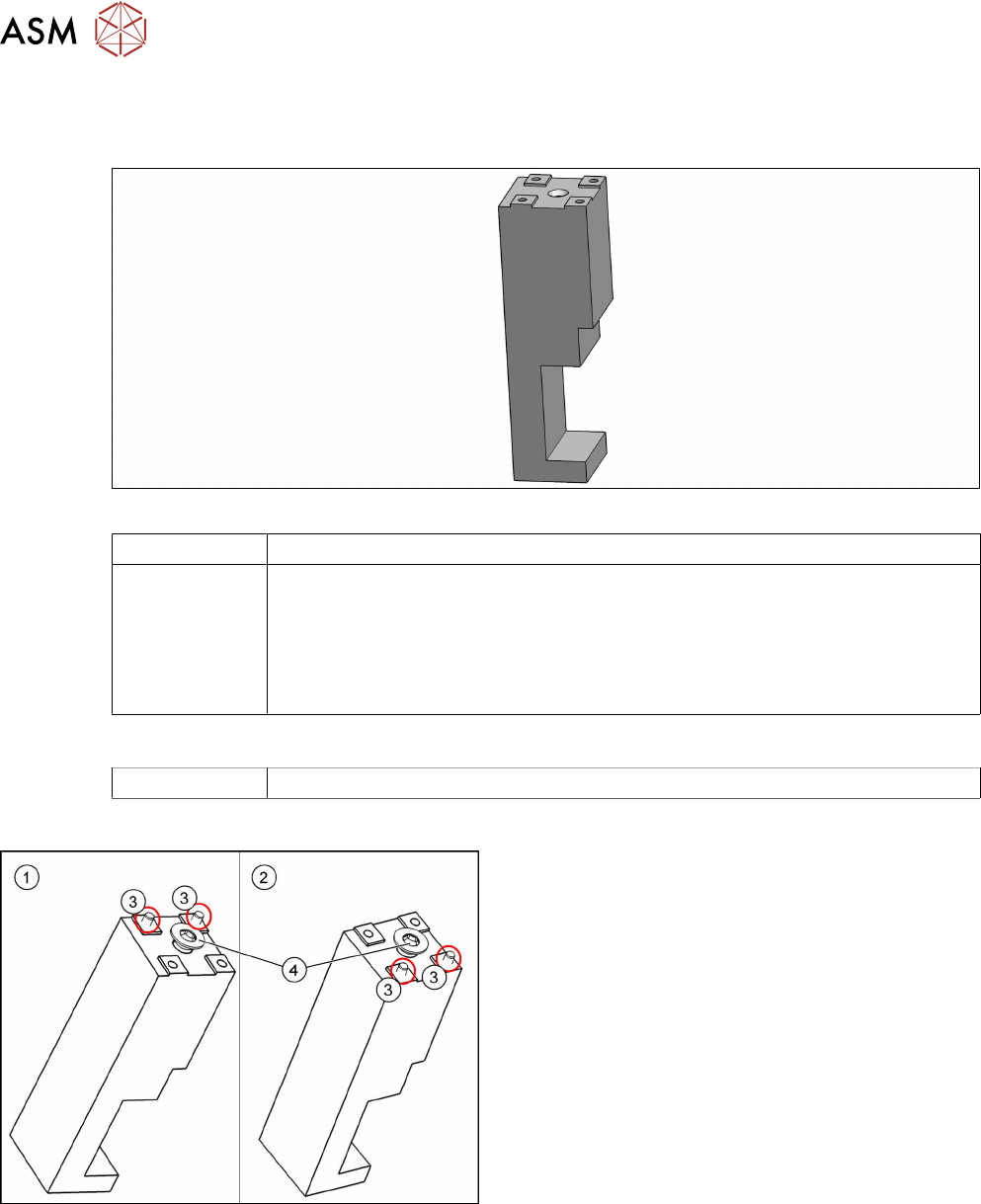
Fig.10: Plate guide
03119681‑xx Plate guide RC
03119681Sxx Plate guide RC (spare parts kit)
Includes:
●
Plate guide RC [03119681‑xx]
●
Self-cutting screw REMFORM RF-SN85-6 x 20-9.8 [03034122‑xx]
●
2x pin ISO 8734 - 3 x 12 - A-ST [03015751‑xx]
Equipment and tools
00376503-xx Torx L-Wrench Set with Spherical head (Torx 30)
Overview
Fig.11: Plate guide
1. Plate guide 1
2. Plate guide 2
3. Pins
4. Self-cutting screw
4 Replacing spare parts at the conveyor
4.2 Lifting table
Service Manual ASM ProcessLens Dual-lane 09/2018 41
Fig.12: Pins on the plate guides
1. Plate guide 1
2. Plate guide 2
TTransport direction
Removal
► Use the software or manually move the conveyor rail into a position which allows you best
access.
– To move the conveyor rail manually, pull the toothed belt of the width adjustment unit.
► Switch off the machine, disconnect it from the power supply and secure it to prevent
unauthorized reactivation.
► Dismantle the lifting table plate (see 4.2.1 "Replacing the lifting table plate" [}38]).
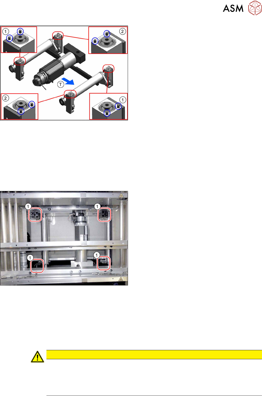
Fig.13: Plate guides
► Remove the relevant plate guide(1).
Installation
► Press in the two pins at the plate guide. Consider the right position depending on the position
in the lifting table. The pins are always on the outside position of the table.
► Insert the self-cutting screw in the center. You can precut the hole with this screw.
► Follow the removal instructions in reverse order for further installation. Also observe the fol-
lowing instructions:
CAUTION
Installation instructions
► Place the lifting table plate onto the guidance pins. Make sure that the fastening
screws slide properly into the precut thread.
► Check the free movement of the lifting table (see Checking free movement of lifting
table).
4 Replacing spare parts at the conveyor
4.2 Lifting table
42 Service Manual ASM ProcessLens Dual-lane 09/2018
4.2.3 Replacing the lifting table motor
Parts
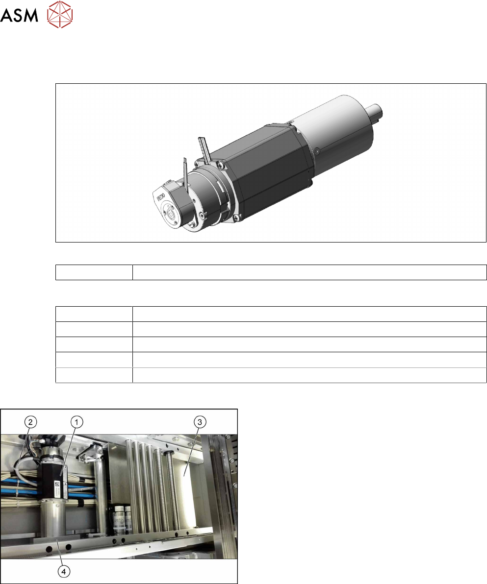
Fig.14: Lifting Table Motor
03088241-xx BLDC motor BG65x50 complete with cable and plug
Equipment and tools
00353832-xx Allen key set
00096290-xx Fork wrench set
00376503-xx Torx L-Wrench Set with Spherical head (Torx 30)
Side cutter
Cable tie
Overview
Fig.15: Lifting table motor - overview
1. Lifting Table Motor
2. Lifting table motor cable (connection to TSP420)
3. TSP420 (under the cover)
4. Retaining bracket for the lifting table motor