00900194-01_SM_ASM ProcessLens_Dual-lane_EN.pdf - 第76页
4 Replacing spare parts at the conveyor 4.6 Fiber optic cables and laser light barriers 76 Service Manual ASM ProcessLens Dual-lane 09/2018 Fig.58: Transmitter and receiver 1. Receiver 2. Transmitter (incl. assembly mat…
4 Replacing spare parts at the conveyor
4.6 Fiber optic cables and laser light barriers
Service Manual ASM ProcessLens Dual-lane 09/2018 75
4.6 Fiber optic cables and laser light barriers
4.6.1 Replacing the laser light barrier for the transmitter/receiver
Parts
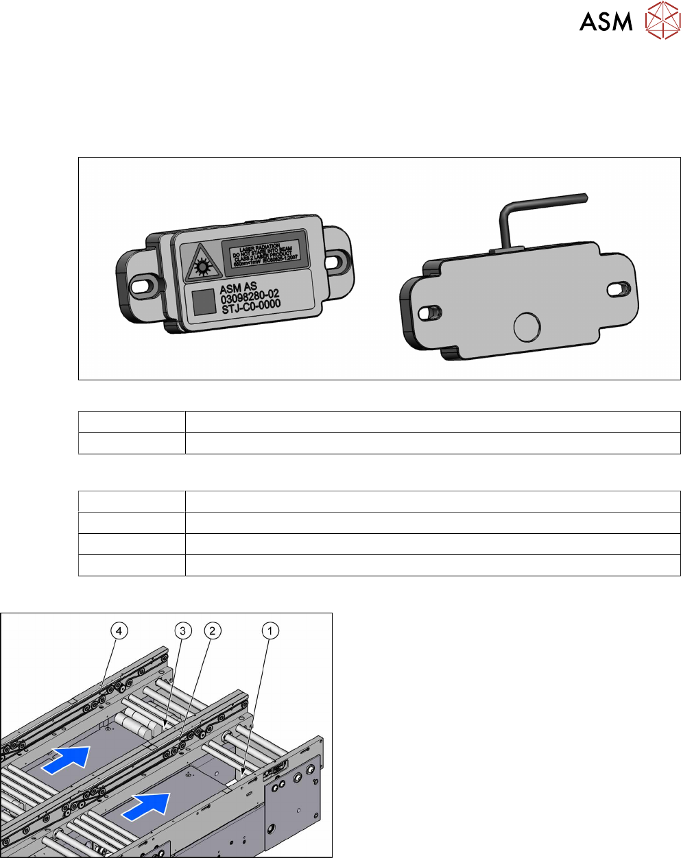
Fig.56: Laser light barrier transmitter and receiver
03098280‑xx Laser light barrier transmitter
03098281‑xx Laser light barrier receiver
Equipment and tools
00353832-xx Allen key set
Flash light
Magnet lifter
Tweezers
Overview
Fig.57: Transmitter and receiver
1. Transmitter PA (track 1)
2. Receiver PA (track 1)
3. Transmitter PA (track 2)
4. Receiver PA (track 2)
4 Replacing spare parts at the conveyor
4.6 Fiber optic cables and laser light barriers
76 Service Manual ASM ProcessLens Dual-lane 09/2018
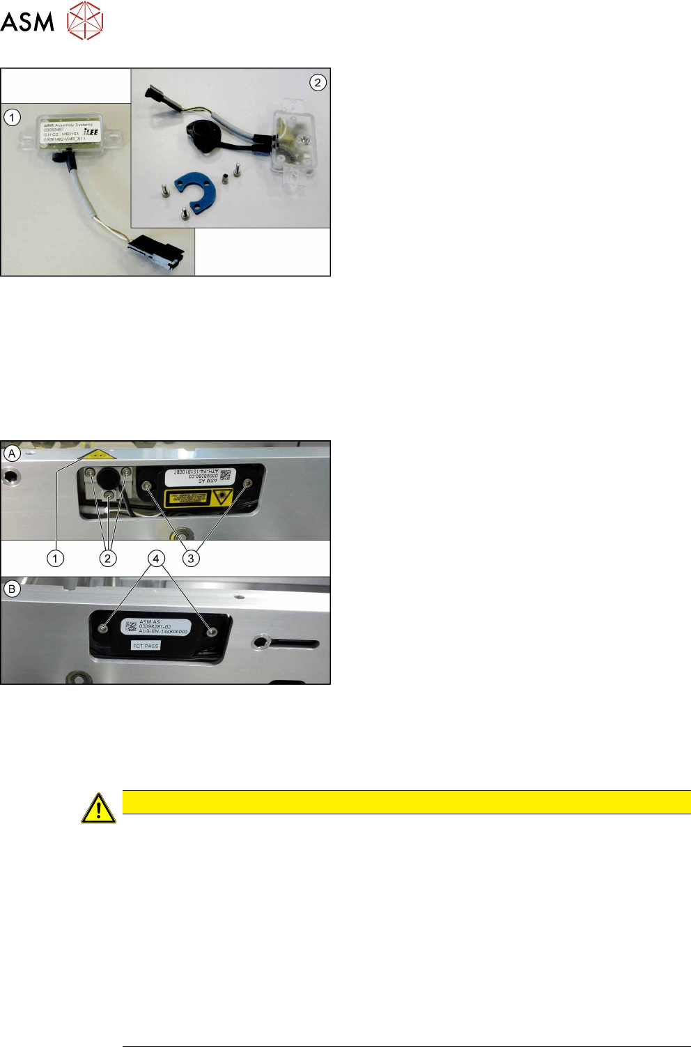
Fig.58: Transmitter and receiver
1. Receiver
2. Transmitter (incl. assembly material)
Removal
► Use the software or manually move the conveyor rail into a position which allows you best
access.
– To move the conveyor rail manually, pull the toothed belt of the width adjustment unit.
► Switch off the machine, disconnect it from the power supply and secure it to prevent
unauthorized reactivation.
Fig.59: Removing transmitter and receiver
The transmitters are always near the laser warning
labels(1). The receivers are always on the opposite
rails.
► (A) Transmitter:
Remove the five fastening screws(2) and(3).
Make sure that no parts fall into the conveyor rail.
► (B) Receiver:
Remove the two fastening screws(4). Make sure
that no parts fall into the conveyor rail.
► Unplug the electrical connection.
Installation
► Follow the removal instructions in reverse order for installation. Also observe the following
instructions:
CAUTION
Installation instructions
► Reconnect the transmitter/receiver before installation.
► Make sure that all the other cables in the conveyor rail are run under the transmitter/
receiver. There is a particular lack of space at the transmitters.
► Use the bushing for the bottom screw. This screw is used to fix the sensor.
The two upper screws are used to adjust the laser beam.
► The transmitters are fixed hand-tight with the lower screw and adjusted with the top
two screws.
► Check the setting for the transmitter / receiver and correct it if necessary (see 4.6.4.1
"Setting the fiber optic sensor" [}85]).
► Teach the PCB sensors using the station software (see Teaching the PCB sensors
(SW70x)).
4 Replacing spare parts at the conveyor
4.6 Fiber optic cables and laser light barriers
Service Manual ASM ProcessLens Dual-lane 09/2018 77
4.6.2 Correcting the laser light barrier setting
DANGER
Laser Class 2
The laser light barrier transmitter emits class 2 laser beams. You therefore do not require
additional protective measures!
► However, you should never look into the laser beam.
► Adjust the laser beam only from the rear side of the laser!
Equipment and tools
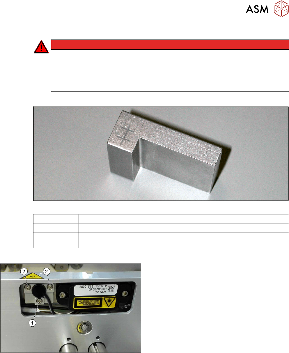
Fig.60: Setting gauge
00369205-xx Setting gauge for conveyor laser light barrier (optional)
00353832-xx Allen key set
Semi-transparent paper or plastic (recommendation for better recognition of the
laser beam)
Overview
Fig.61: Laser light barrier
1. Fastening screw
2. Setting screws