00900194-01_SM_ASM ProcessLens_Dual-lane_EN.pdf - 第60页
4 Replacing spare parts at the conveyor 4.4 Width adjustment 60 Service Manual ASM ProcessLens Dual-lane 09/2018 4.4.3 Replacing the clamping unit Parts Fig.35: Clamping unit 03121328-xx Clamping unit 4 complete M-C Equ…
4 Replacing spare parts at the conveyor
4.4 Width adjustment
Service Manual ASM ProcessLens Dual-lane 09/2018 59
Overview
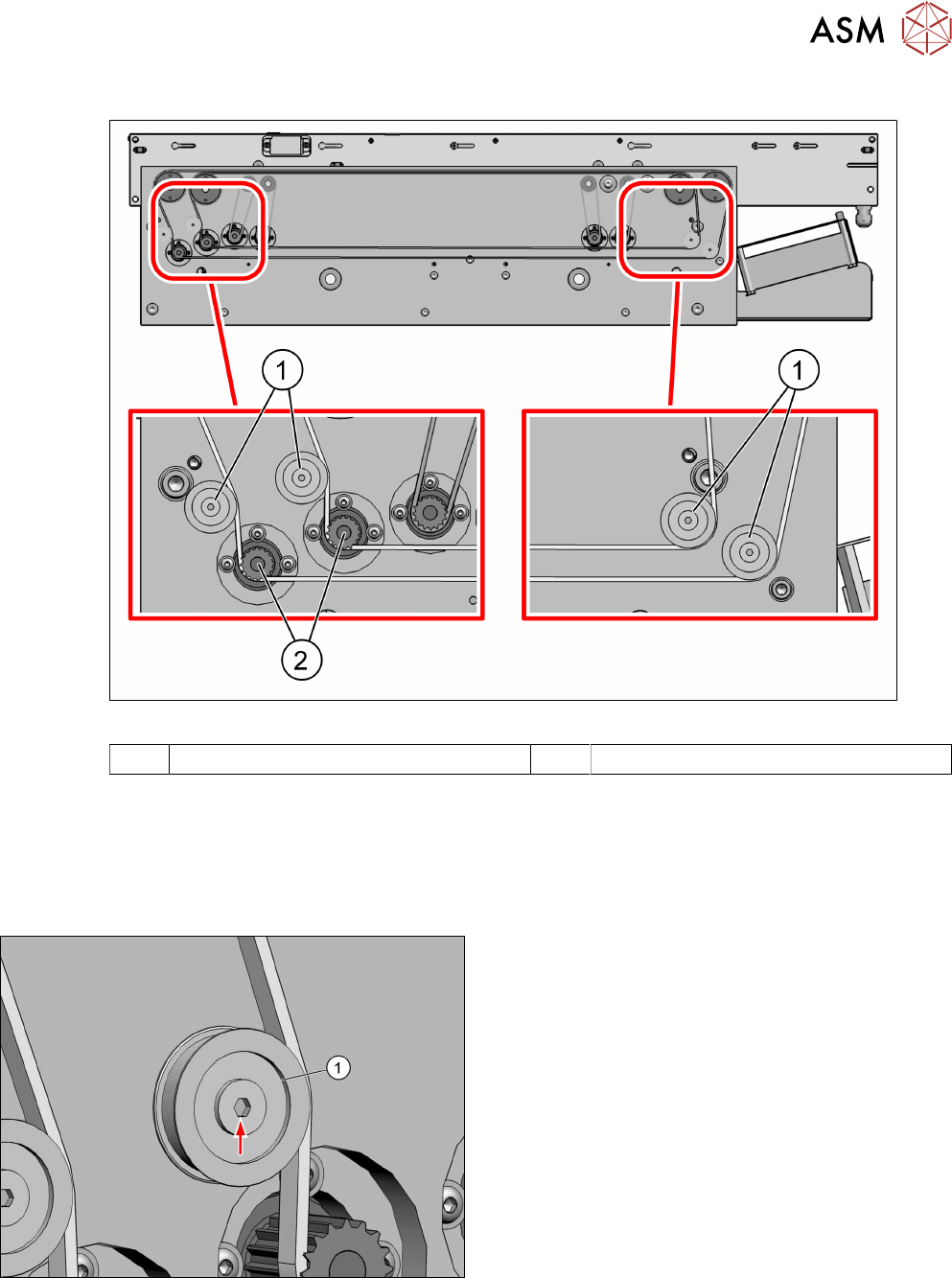
Fig.33: Overview of idler pulleys (width adjustement)
1 Deflection pulleys 2 Width adjustment motor
Removal
► Switch off the machine, disconnect it from the power supply and secure it to prevent
unauthorized reactivation.
► Loosen the toothed belt (width adjustment).
Replacing the toothed belt (width adjustment)
Fig.34: Idler pulley
► Remove the fastening screw of the idler pulley(1)
and take the idler pulley off.
Installation
► Fasten the idler pulley with a screw.
► For further installation, proceed as described in section Replacing the toothed belt (width ad-
justment).
4 Replacing spare parts at the conveyor
4.4 Width adjustment
60 Service Manual ASM ProcessLens Dual-lane 09/2018
4.4.3 Replacing the clamping unit
Parts
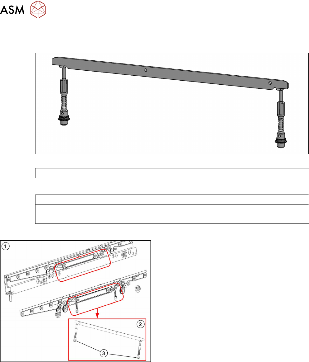
Fig.35: Clamping unit
03121328-xx Clamping unit 4 complete M-C
Equipment and tools
02101037‑xx Loctite 241
00353832-xx Allen key set
00376503-xx Torx L-Wrench Set with Spherical head (Torx 30)
Overview
Fig.36: Clamping unit
1. Clamping unit on conveyor rail
2. Clamping unit complete
3. actuator
4 Replacing spare parts at the conveyor
4.4 Width adjustment
Service Manual ASM ProcessLens Dual-lane 09/2018 61
Removal
CAUTION
Small parts
► Take care not to lose any small parts.
► Take particular care not to let the screws fall into the conveyor rail when removing the
screws or clamping plate.
► Use the software or manually move the conveyor rail into a position which allows you best
access.
– To move the conveyor rail manually, pull the toothed belt of the width adjustment unit.
► Switch off the machine, disconnect it from the power supply and secure it to prevent
unauthorized reactivation.
► Remove the lifting table plate to make room for removing the actuator later (see chapter 4.2.1
"Replacing the lifting table plate" [}38]).
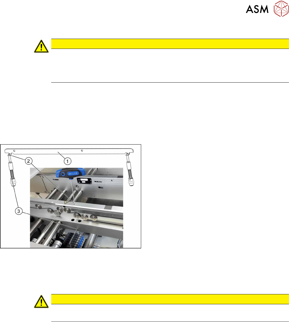
Fig.37: Removing clamping plate
► Insert the small pin or Allen key(3) to fix the
actuator.
► Remove the two screws(2) fastening clamping
plate(1).
First loosen one screw slightly, and then loosen
the other screw slightly. After that, remove both
screws completely.
► Remove inserted Allen key and remove the
actuator from bottom side.
► Remove the clamping plate(1) with two fastening
screws carefully.
Installation
► Follow the removal instructions in reverse order for installation. Also observe the following
instructions:
CAUTION
Installation instructions
► Secure the two screws fastening the clamping unit with Loctite 241.