00900194-01_SM_ASM ProcessLens_Dual-lane_EN.pdf - 第54页
4 Replacing spare parts at the conveyor 4.3 Conveyor drive 54 Service Manual ASM ProcessLens Dual-lane 09/2018 Overview Fig.27: Overview of cables
4 Replacing spare parts at the conveyor
4.3 Conveyor drive
Service Manual ASM ProcessLens Dual-lane 09/2018 53
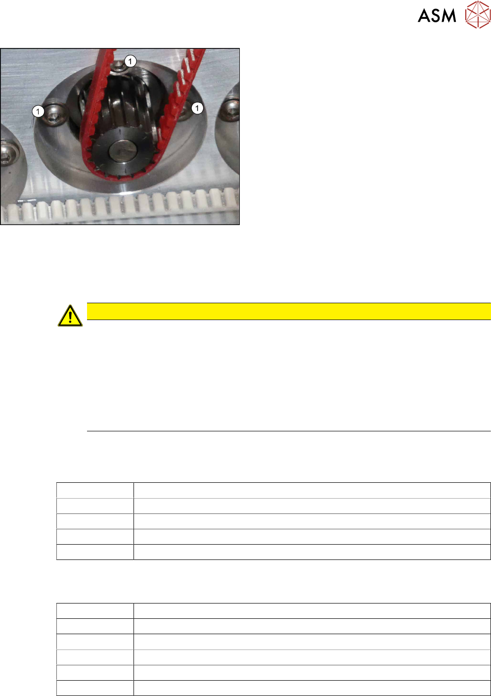
Fig.26: Fastening screws
► Loosen the three screws (1) fastening the con-
veyor drive.
► Carefully unthread the toothed belt from the mo-
tor.
Installation
► Follow the removal instructions in reverse order for installation. Also observe the following
instructions:
CAUTION
Installation instructions
► Make sure that the toothed belt is not folded or otherwise damaged.
► Make sure that the toothed belt is accurately positioned in the guidance on the motor
shaft.
► Carefully thread in the toothed belt. To do this, carefully lift the toothed belt a little (e.g.
with the shorter end of an Allen key).
► Tighten the three screws fastening the conveyor drive hand-tight. At the same time,
adjust the belt tension to 210+/‑20Hz.
4.3.3 Replacing the cables (belt motor and width adjustment motor)
Parts
03113852-xx Sensor cable belt motor output track 1
03113854‑xx Motor cable width adjustment track 1
03113870-xx Motor cable belt motor output track 1
03113871‑xx Motor cable width adjustment track 1
03088836‑xx Cable CAN bus internal conveyor controller SX2
See also 4.6.5 "Replacing laser light barrier cables and fiber optic cables" [}90]
Equipment and tools
02101037‑xx Loctite 241
00353832-xx Allen key set
00096290-xx Fork wrench set
00376503-xx Torx L-Wrench Set with Spherical head (Torx 30)
Side cutter
Cable tie
4 Replacing spare parts at the conveyor
4.3 Conveyor drive
54 Service Manual ASM ProcessLens Dual-lane 09/2018
Overview
Fig.27: Overview of cables
4 Replacing spare parts at the conveyor
4.3 Conveyor drive
Service Manual ASM ProcessLens Dual-lane 09/2018 55
Removal
CAUTION
Do not loosen the wrong screws
Make sure that you do not loosen any other screws except those ones explicitly mentioned.
Loosening other screws could lead to irreparable misalignment or damage to the conveyor.
► Use the software or manually move the conveyor rail into a position which allows you best
access.
– To move the conveyor rail manually, pull the toothed belt of the width adjustment unit.
► Switch off the machine, disconnect it from the power supply and secure it to prevent
unauthorized reactivation.
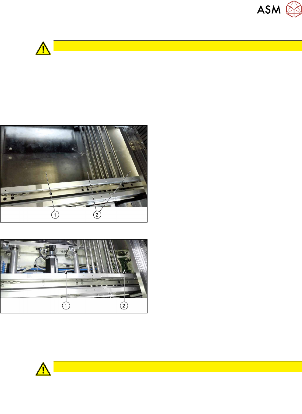
Fig.28: Table plate and covers
► Remove the four screws fastening the lifting table
plate(1) (see also 4.2.1 "Replacing the lifting
table plate" [}38]).
► Remove the fixing spacer bolts of the covers(2)
above the conveyor control (two screws each
cover) and remove the covers.
Fig.29: Cables
The cables(1) run from the respective motor over the
floor of the conveyor to the conveyor control(2).
► Carefully unthread the cables
Remove any cable ties.
Installation
► Follow the removal instructions in reverse order for installation. Also observe the following
instructions:
CAUTION
Installation instructions
► Observe the installation instructions for the conveyor drive where necessary.
► Replace any open cable ties.
Make sure that the cable ties and the heads of the cable ties do not rub against any
parts when you do this.