00900194-01_SM_ASM ProcessLens_Dual-lane_EN.pdf - 第83页
4 Replacing spare parts at the conveyor 4.6 Fiber optic cables and laser light barriers Service Manual ASM ProcessLens Dual-lane 09/2018 83 Fig.67: Plug-and-socket connections WARNING! The adjacent fiber optic sensors…
4 Replacing spare parts at the conveyor
4.6 Fiber optic cables and laser light barriers
82 Service Manual ASM ProcessLens Dual-lane 09/2018
4.6.4 Replacing the fiber optic sensor
Parts
Fig.65: Fiber optic sensor
03093294-xx Fiber optic sensor WLL180T-M pre-programmed SXa (master)
03093295-xx Fiber optic sensor WLL180T-F pre-programmed SXa (slave)
Equipment and tools
00353832-xx Allen key set
Side cutter
Cable ties
Overview
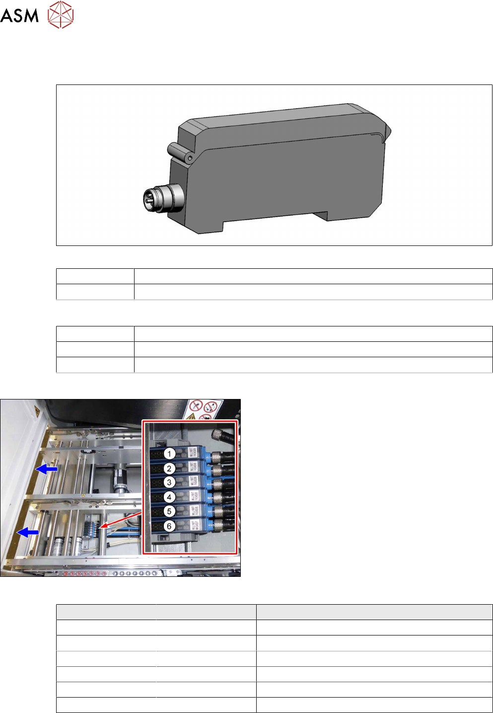
Fig.66: Fiber optic sensors
The fiber optic sensors are located at location 2 under
the lifting table plate.
(1) to (6): fiber optic sensors for the input area, place-
ment area and output area.
The receivers are always at the top of the fiber optic
sensors and the transmitters at the bottom.
Conveyor track Designation Description
Track 1 1 (slave) Output area
2 (slave) Placement area
3 (slave) Input area
Track 2 4 (slave) Output area
5 (slave) Placement area
6 (master) Input area
4 Replacing spare parts at the conveyor
4.6 Fiber optic cables and laser light barriers
Service Manual ASM ProcessLens Dual-lane 09/2018 83
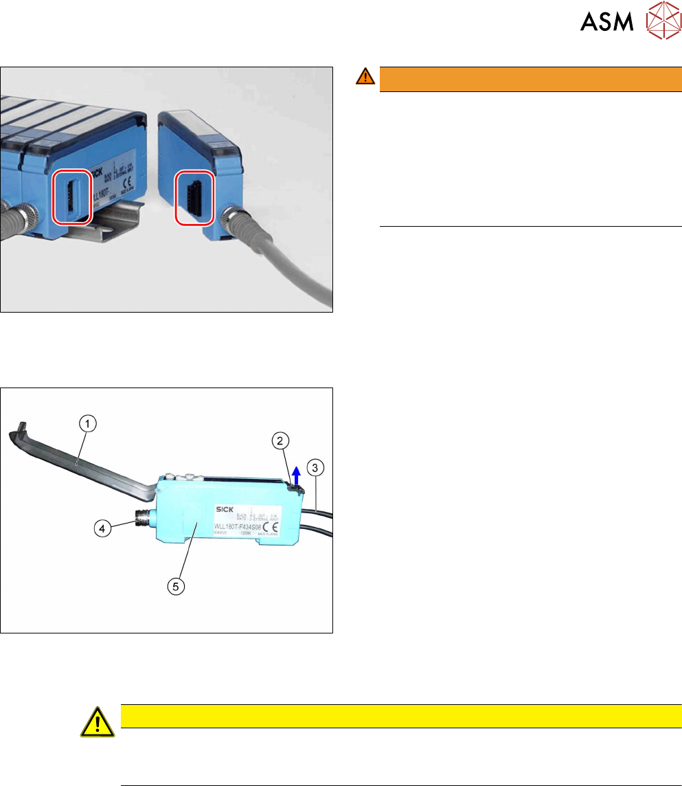
Fig.67: Plug-and-socket connections
WARNING!
The adjacent fiber optic sensors are connec-
ted via plug-and-socket connections on the
side.
Before dismantling the fiber optic sensors always
separate them a bit.
Do not lift the fiber optic sensors off without sep-
arating them first. If you do so, you may damage
the plug-and-socket connection.
.
Each sensor has two fiber optic cables connected (transmitter/receiver), which belong to the same
conveyor belt (segment).
Fig.68: Fiber optic sensor
1. Cover
2. Locking the fiber optic cables
top = open
bottom = closed
3. Fiber optic cable
Top: input (from receiver)
Bottom: output (to transmitter)
4. Electrical connection
5. Electrical connection to neighboring fiber optic
sensor (under the plastic cover)
Removal
CAUTION
Do not bend fiber optic cables
► Make sure you do not bend the fiber optic cables. Otherwise the cable will become
cloudy and no longer transmit the signal properly.
► Use the software or manually move the conveyor rail into a position which allows you best
access.
– To move the conveyor rail manually, pull the toothed belt of the width adjustment unit.
► Switch off the machine, disconnect it from the power supply and secure it to prevent
unauthorized reactivation.
4 Replacing spare parts at the conveyor
4.6 Fiber optic cables and laser light barriers
84 Service Manual ASM ProcessLens Dual-lane 09/2018
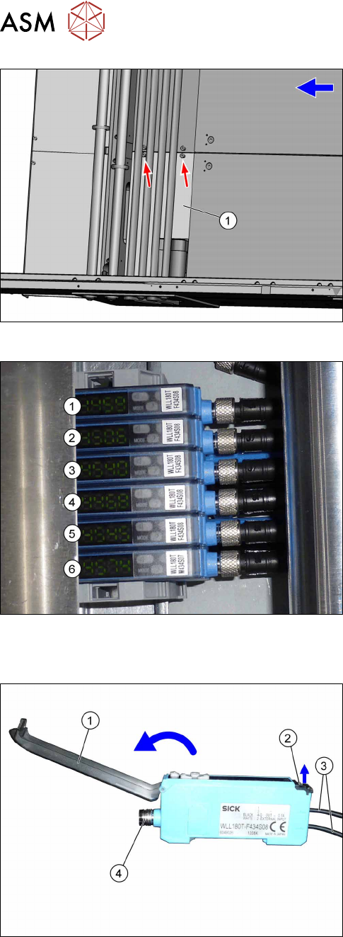
Fig.69: Cover
► Remove the two screws fastening the cover(1)
and remove the cover.
Fig.70: Fiber optic sensors
The individual fiber optic sensors are connected to
one another via a small terminal strip.
Dismantle the fiber optic sensors one after one begin-
ning with (6) (track2) until you have reached the fiber
optic sensor to be replaced. Perform the following
tasks at each fiber optic sensor:
Dismantling a fibre optic sensor
Fig.71: Fiber optic sensor
► Open the cover(1) on the fiber optic sensor.
► Open the lock(2) on the fiber optic cables(3) and
then pull off the fiber optic cables. You might like
to mark their positions to make clear assignment
easier later on.
► Disconnect from the power supply(4). You may
want to mark the position, to make clear assign-
ment easier later on.
► Pull the fiber optic sensor slightly away from the other fiber optic sensors, to loosen the elec-
trical connection to the neighboring fiber optic sensor.
Now you can pull the sensor up and off the strip.
► Repeat these steps if needed for any other fiber optic sensors.