00900194-01_SM_ASM ProcessLens_Dual-lane_EN.pdf - 第7页
1 Introduction 1.1 Safety instructions Service Manual ASM ProcessLens Dual-lane 09/2018 7 1.1.4 Residual voltages and discharge times in the machine 1.1.4.1 Energy state of the machine after the EMERGENCY STOP button is …
1 Introduction
1.1 Safety instructions
6 Service Manual ASM ProcessLens Dual-lane 09/2018
1.1.2 Safety instructions for working with strong magnetic fields
DANGER
Strong permanent magnetic fields
Fatal hazard: persons with active implants (e.g. pacemakers, defibrillators, insulin pumps,
etc.) are at risk from strong permanent magnetic fields inside the machine.
Persons at risk should avoid the immediate vicinity of the machine.
CAUTION
Danger of crushing
Danger of crushing for persons with passive metal implants (e.g. plates, screws).
► Do not reach or lean over into the machine when the covers are open.
► Do not bring any metal objects into the danger area.
CAUTION
Strong permanent magnetic fields
There is a risk that the strong magnetic fields could corrupt data on data media or check
cards.
► Keep sensitive data media away from the permanent magnets.
1.1.3 Safety instructions for the power supply (without SMPS)
DANGER
The system is electrically driven. When electrical devices are in use, certain parts
carry dangerous voltage levels
There is a risk of death, severe injury and/or considerable damage to equipment if these
instructions are not followed.
► Switch off the main switch and disconnect the ASM ProcessLens solder paste inspec-
tion machine from the power supply before carrying out any work on live components.
●
This means that some parts of the system carry potentially lethal voltages - even when
switched off at the main power switch.
●
Incorrect handling of the solder paste inspection system can therefore result in fatal injuries,
severe injuries or considerable damage to equipment.
●
Measurements and maintenance work must always be carried out by appropriately qualified
personnel.
●
Always follow the applicable accident prevention and DIN regulations (particularly DIN EN 60
204, part 1) or the regulations specific to your country.
●
Before starting any maintenance work, switch the machine off at the main switch and discon-
nect it from the main power supply.
●
Always secure the machine against unauthorized reactivation. If these instructions are not
followed, you may be able to touch live parts, which could result in fatal or severe injuries.
Maintaining, Installing or Removing Assemblies
► End all inspection operations on the machine.
► Shut down the Windows operating system correctly, otherwise problems may occur when
restarting or data may be lost.
► Switch the machine off at the main switch.
► Disconnect the machine from the main power supply.
► Switch off the machine and attach warnings signs to indicate that service work is in progress.
1 Introduction
1.1 Safety instructions
Service Manual ASM ProcessLens Dual-lane 09/2018 7
1.1.4 Residual voltages and discharge times in the machine
1.1.4.1 Energy state of the machine after the EMERGENCY STOP button is pressed
If the EMERGENCY STOP button is pressed, the voltage are reduced to harmless residual
voltages in a very short time.
WARNING
Some parts of the system carry potentially lethal voltages
The machine is supplied with 1/N/PE ~ 240, 50/60 Hz mains voltage. This means that some
parts of the system carry potentially lethal voltages - even when switched off at the main
power switch. Incorrect handling of the machine can therefore result in death or severe in-
jury or considerable damage to equipment.
► Always follow the applicable accident prevention and safety regulations (particularly
DIN EN 60204, part 1 or IEC 60204, part 1) and the safety regulations in your own
country.
► The covers over the power supply unit may ONLY be opened by appropriately quali-
fied and trained personnel.
NOTICE
ASM ProcessLens Dual-lane electrical diagrams
For details, please refer to the ASM ProcessLens Dual-lane electrical diagrams.
1.1.4.2 Energy state of the machine after switching off the main power switch
WARNING
Some parts of the system carry potentially lethal voltages
The machine is supplied with 1/N/PE ~ 240, 50/60 Hz mains voltage. This means that some
parts of the system carry potentially lethal voltages - even when switched off at the main
power switch. Incorrect handling of the machine can therefore result in death or severe in-
jury or considerable damage to equipment.
► Always follow the applicable accident prevention and safety regulations (particularly
DIN EN 60204, part 1 or IEC 60204, part 1) and the safety regulations in your own
country.
The following components still carry potentially lethal voltages even if the main power switch is
switched off:
●
Mains connection terminals of the main power switch.
NOTICE
ASM ProcessLens Dual-lane electrical diagrams
For details, please refer to the ASM ProcessLens Dual-lane electrical diagrams.
To avoid losing data, assess the following criteria before switching off your machine (apart from in
emergencies):
●
Has the machine finished transmitting machine and recipe data?
●
Has the machine finished processing the PCB?
●
Has the machine software completed the shot-down phase?
Machine switched off at the main power switch and disconnected
The machine is unpowered, apart from slight residual voltages in the power supply unit.
1 Introduction
1.2 Lock out and tag out procedure
8 Service Manual ASM ProcessLens Dual-lane 09/2018
1.1.5 Safety instructions for the gantry
CAUTION
Moving the gantry can damage the placement head.
When moving the gantry, observe the following:
► NEVER move the gantry by pushing with your hands against the placement head.
1.1.6 Safety instructions on hazardous materials
CAUTION
Observe the safety data sheets
Observe the applicable safety data sheet, when handling hazardous materials (e. g. Loctite
241, ethanol).
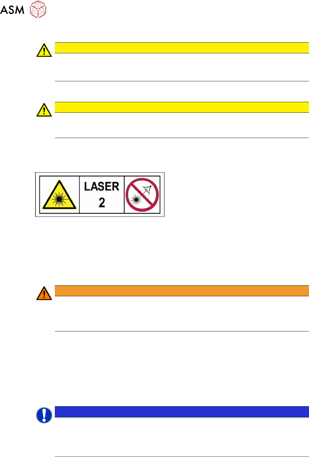
1.1.7 Classification of the optical systems
1.1.7.1 Classification of the whole machine
Fig.1: Laser class 2
The ready-to-operate overall machine is assigned
to laser class°2.
The laser classes are determined according to
DIN EN 60825-1:2014.
1.1.7.2 Laser classification
The following modules are assigned to laser class 2:
●
Laser light barriers at the board conveyor
1.1.7.3 Classification of the camera systems
WARNING
LEDs
The camera illumination systems are fitted with light LEDs. These are assigned to risk
group 1 according to IEC 62741:2006.
► Do not look into beam!
1.2 Lock out and tag out procedure
1.2.1 Purpose and scope
Before performing any preventive maintenance work, conversion work or service work, a procedure
of locking and tagging must be followed and warning signs must be attached if not stated other-
wise. If it is not necessary to switch off the machine, it is explicitly mentioned.
The procedure, when followed, correctly eliminates the possibility of an employee being injured.
NOTICE
Additional safety measures
These procedures represent the minimum lock/tag out requirements for the machine during
preventive maintenance work and service work. Any additional safeguards needed to com-
plete work safely can be specified by facilities supervision, the safety officer, the safety
committee and the health department.