00900194-01_SM_ASM ProcessLens_Dual-lane_EN.pdf - 第63页
4 Replacing spare parts at the conveyor 4.5 Conveyor belt, belt drive and hexagonal shaft Service Manual ASM ProcessLens Dual-lane 09/2018 63 4.5 Conveyor belt, belt drive and hexagonal shaft 4.5.1 Replacing the toothed …
4 Replacing spare parts at the conveyor
4.4 Width adjustment
62 Service Manual ASM ProcessLens Dual-lane 09/2018
4.4.4 Calibrating the Track Zero Point
After completing all work to the width adjustment (adjustment unit, motor or belt of width adjust-
ment), you need to configure the adjustment unit before you configure the conveyor sides.
Procedure
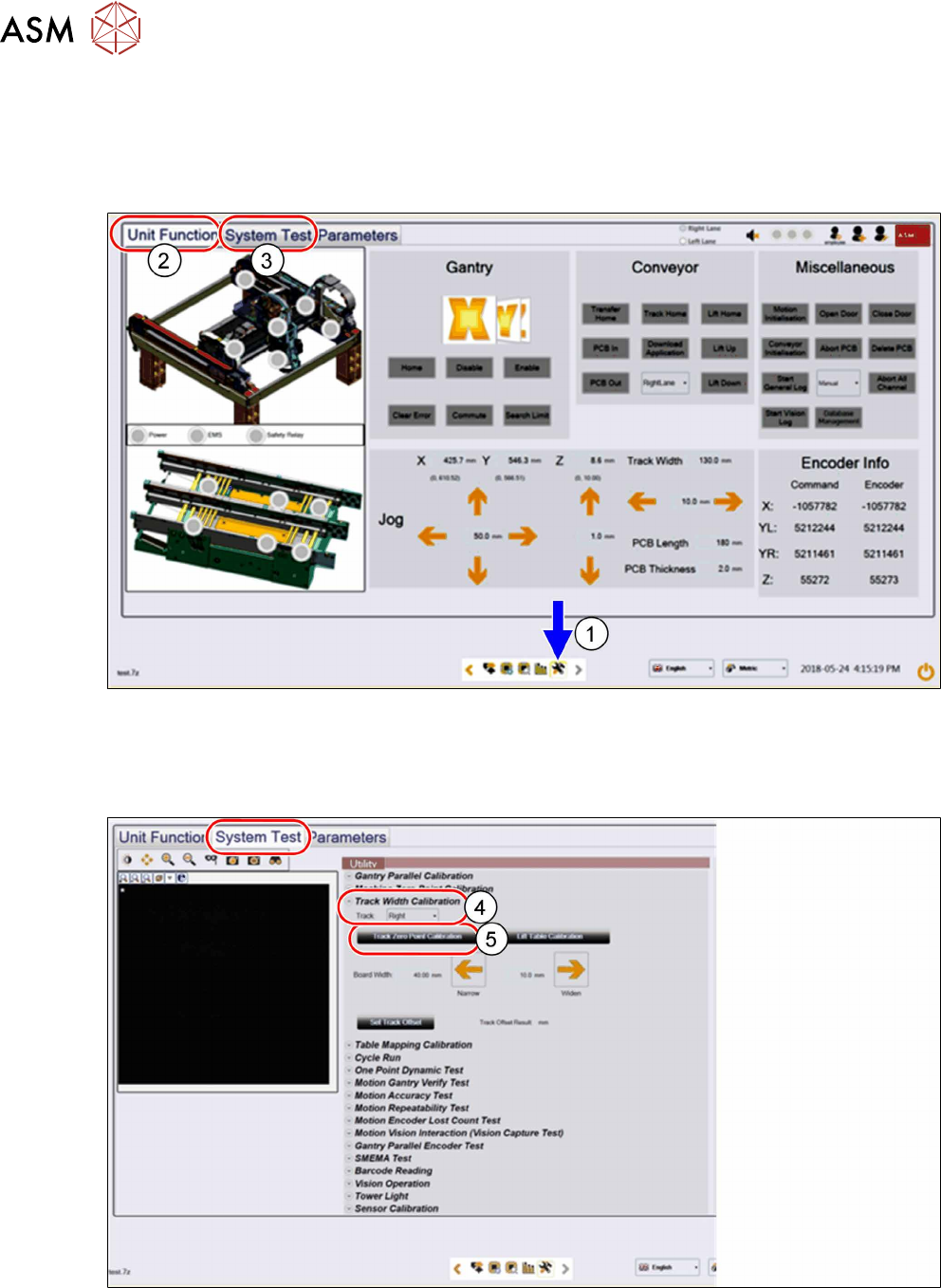
► Click on this icon(1) to enter the settings menu.
► Click on Unit Function(2) to enter the settings user menu.
► Switch to operator level Machine service.
► Click on System Test(3) to enter the calibration menu.
► In the Track Width Calibration area(4) select the right track.
► Click on the Track Zero Point Calibration button(5) to calibrate the track zero point of the
right track.
► Repeat the calibration the same way for the left track.
4 Replacing spare parts at the conveyor
4.5 Conveyor belt, belt drive and hexagonal shaft
Service Manual ASM ProcessLens Dual-lane 09/2018 63
4.5 Conveyor belt, belt drive and hexagonal shaft
4.5.1 Replacing the toothed belt (conveyor belt)
Parts
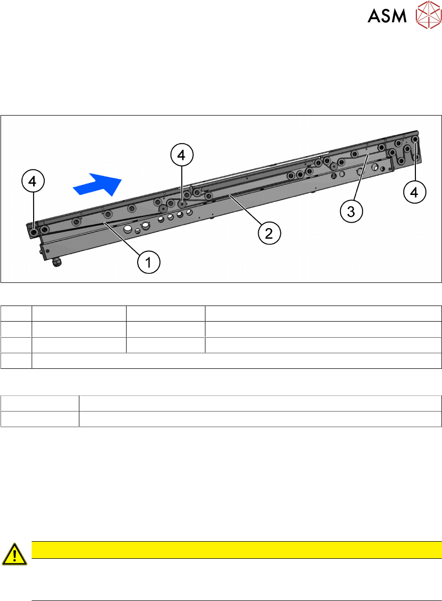
Fig.38: Toothed belt (conveyor belt) and movable idler pulleys
1 Input area 03172246-xx Belt L=897mm
2 Placement area 03121441-xx Synchronous belt L=843mm
3 Output area 03121441xx Belt L=843mm
4 Movable idler pulleys (see Replacing the idler pulley (conveyor belt))
Equipment and tools
00326015‑xx Belt tension measuring device
00353832-xx Allen key set
Removal
► Use the software or manually move the conveyor rail into a position which allows you best
access.
– To move the conveyor rail manually, pull the toothed belt of the width adjustment unit.
► Switch off the machine, disconnect it from the power supply and secure it to prevent
unauthorized reactivation.
► Loosen the movable idler pulley.
CAUTION
Loosen the movable idler pulley only as far as necessary!
► Do not remove the movable idler pulley. Otherwise the T slot nut on the inner side will
fall into the conveyor rail.
► Carefully unthread the belt drive.
Installation
► Check the new toothed belt before fitting it. Hold it up high. It should hang loose and should
not twist.
► Follow the removal instructions in reverse order for further installation. Also observe the fol-
lowing instructions:
– Do not bend or damage the toothed belt.
– Make sure that the toothed belt is positioned accurately in the guidance on the motor
shaft / belt drive.
– When you tighten the idler pulley, set the tension of the toothed belt (see below).
4 Replacing spare parts at the conveyor
4.5 Conveyor belt, belt drive and hexagonal shaft
64 Service Manual ASM ProcessLens Dual-lane 09/2018
4.5.2 Setting the belt tension
The precalculated values for setting the belt tension can be found in the following chapters.
In addition, the value for any section of the conveyor belt can be calculated using a formula (see
4.5.2.2 "Calculating the belt tension" [}65]).
4.5.2.1 Setting the tension of the conveyor toothed belt
Equipment and tools
00326015‑xx Belt tension measuring device
00353832-xx Allen key set
Overview of measuring points and values
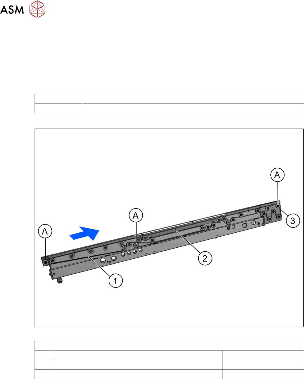
Fig.39: Measuring points
A Movable idler pulleys
1 Measuring point on the toothed belt in the input area 45 +/- 4.5 Hz
2 Measuring point on the toothed belt in the placement area 62 +/- 5 Hz
3 Measuring point on the toothed belt in output area 279 +/- 27 Hz