00900194-01_SM_ASM ProcessLens_Dual-lane_EN.pdf - 第78页
4 Replacing spare parts at the conveyor 4.6 Fiber optic cables and laser light barriers 78 Service Manual ASM ProcessLens Dual-lane 09/2018 Procedure with setting gauge Fig.62: Focusing the laser beam (using example of …
4 Replacing spare parts at the conveyor
4.6 Fiber optic cables and laser light barriers
Service Manual ASM ProcessLens Dual-lane 09/2018 77
4.6.2 Correcting the laser light barrier setting
DANGER
Laser Class 2
The laser light barrier transmitter emits class 2 laser beams. You therefore do not require
additional protective measures!
► However, you should never look into the laser beam.
► Adjust the laser beam only from the rear side of the laser!
Equipment and tools
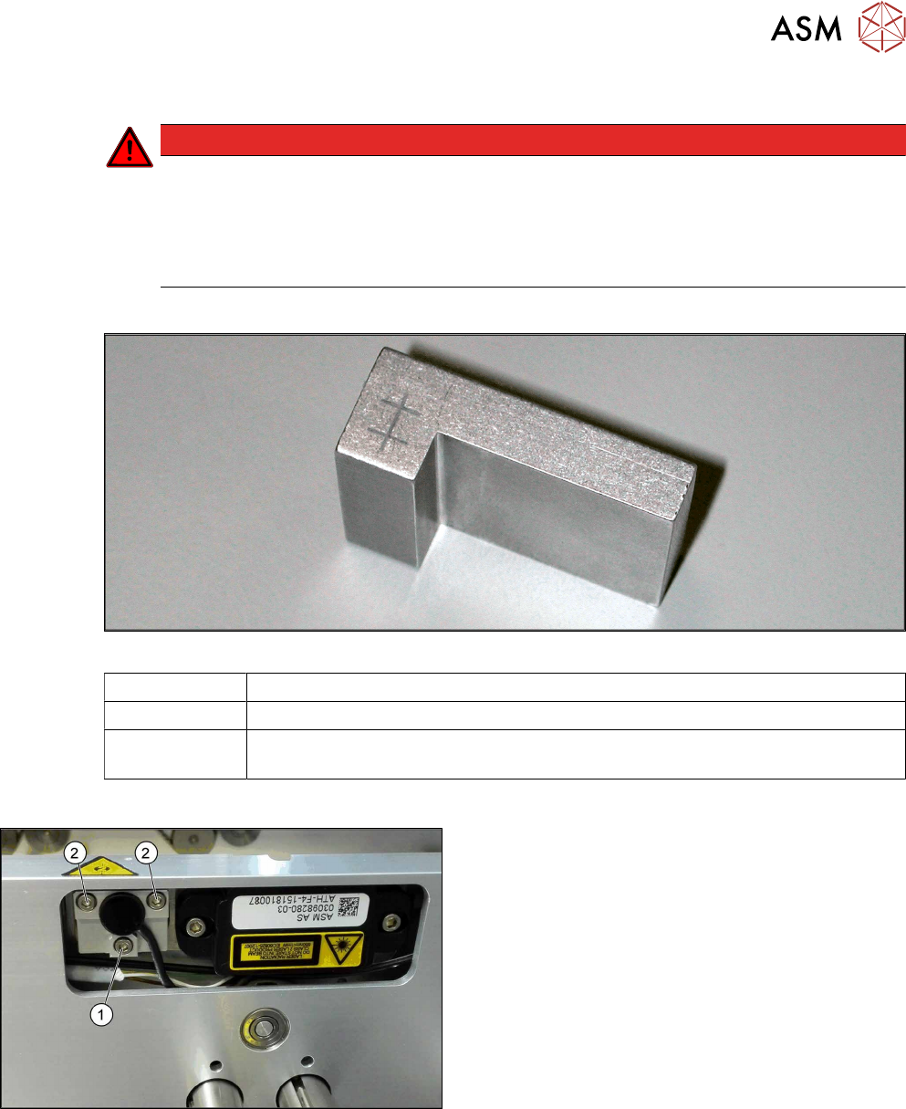
Fig.60: Setting gauge
00369205-xx Setting gauge for conveyor laser light barrier (optional)
00353832-xx Allen key set
Semi-transparent paper or plastic (recommendation for better recognition of the
laser beam)
Overview
Fig.61: Laser light barrier
1. Fastening screw
2. Setting screws
4 Replacing spare parts at the conveyor
4.6 Fiber optic cables and laser light barriers
78 Service Manual ASM ProcessLens Dual-lane 09/2018
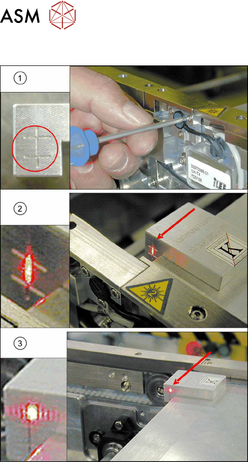
Procedure with setting gauge
Fig.62: Focusing the laser beam (using example of X-Series)
1. Setting the laser light barrier
2. Minimum width
3. Maximum width
► Set the maximum conveyor width.
► Select Enable safety mode in software.
► Activate the relevant laser diode using the input/
output functions in the station software.
► Check the path of the laser beam with the help of
the gauge.
► With the help of the three setting screws, adjust
the laser beam to the center of the gauge cross
(1).
► Now position the conveyor to minimum width(2)
and check the setting.
► Check the PCB reference corner and reteach, if
necessary.

4 Replacing spare parts at the conveyor
4.6 Fiber optic cables and laser light barriers
Service Manual ASM ProcessLens Dual-lane 09/2018 79
4.6.3 Repairing the fiber optic cables
To avoid machine downtimes, it is possible to repair fiber optic cables temporarily, using the repair
hose.
NOTICE
Repair hose for fiber optic cable LL3-TV05
► The repair hose may only be used for short periods to avoid machine downtimes.
► The repair hose may only be used once per fiber optic cable.
► The fiber optic cable must be replaced during the next repair or maintenance cycle.
NOTICE
No guarantee
► No guarantee is given if the fiber optic cable is repaired using the repair hose.
► There is no long-term experience with the repair hose.
► Depending on the board width, the intensity of the light beam may diminish in such a
way that an evaluation is no longer possible.
► The repair hose must not be bended. For this reason, there is an additional danger of
rupture after the repair, in areas where the fiber optic cable is routed in narrow radii.
► If another rupture of the fiber optic cable occurs and it is not possible to replace the whole
fiber optic cable, replace the defective part of the fiber optic cable in such a way that only one
repair hose is used.
Parts
03092407-xx Fibre optic cable LL3-TV05 2m (including cutting tool for fibre optic cables)
03092408-xx Fibre optic cable LL3-TV05 3m (spare part) (including cutting tool for fibre optic
cables)
03122383-xx Hose PUN 3x0.5-SW, 100mm (repair hose)
A repair hose is supplied with each fiber optic cable. The repair hose is not
available as an individual spare part.
Sheet with yellow glue dots
Equipment and tools
03017821-xx Loctite 406 (instant glue highly viscous)
03019481-xx Dosage tip for Loctite
00372972-xx Protective latex gloves
00353832-xx Allen key set
Cable tie
Side cutter