00900194-01_SM_ASM ProcessLens_Dual-lane_EN.pdf - 第20页
3 Replacing spare parts 3.1 Optical head 20 Service Manual ASM ProcessLens Dual-lane 09/2018 ► Unscrew and remove the four screws (1) on the low ring light assembly using an Allen key size 2.5. CAUTION! Different types…
3 Replacing spare parts
3.1 Optical head
Service Manual ASM ProcessLens Dual-lane 09/2018 19
Installation
Follow the removal instructions in reverse order for installation.
3.1.1.1 Check the calibration of the optical head
When the optical head is removed from the machine the optical head needs to be calibrated again.
See the following document on how to do so: Doc. Number 00900064.
3.1.2 Replacing the low ring light board
Parts
03122925-xx PCBA low ring light board
Equipment and tools
●
Allen key size 2.5
●
Philips screwdriver
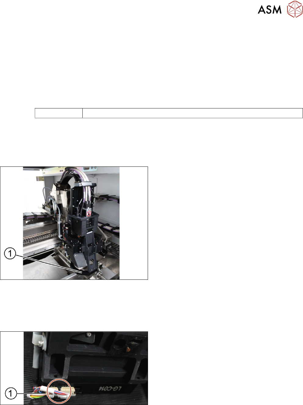
Overview
1. Low ring light assembly
Requirements
●
Machine is switched off.
●
Use a T shaped Allen key to carry out this job.
Removal
► Unplug the connectors (1) at the back of the low
ring light assembly.
3 Replacing spare parts
3.1 Optical head
20 Service Manual ASM ProcessLens Dual-lane 09/2018
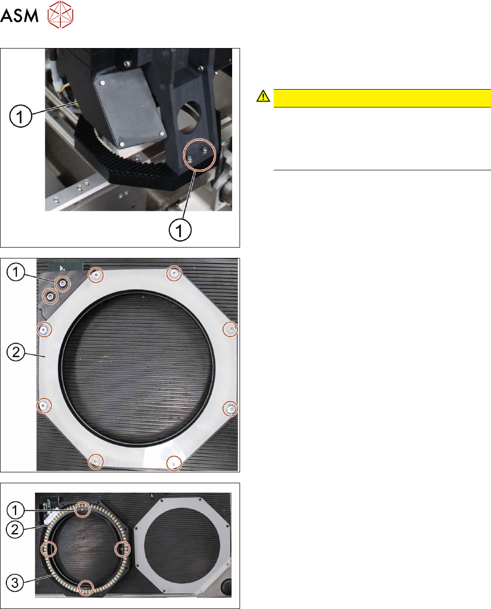
► Unscrew and remove the four screws (1) on the
low ring light assembly using an Allen key size
2.5.
CAUTION!
Different types of screws
There are two different types of screws. The
ones in the back are shorter than the ones in the
front.
Do not interchange the screws.
.
► Remove the low ring light assembly and place it
on a service table.
► Unscrew and remove all screws (1) with an Allen
key size 2.5.
► Remove the cover (2) of the low ring light assem-
bly.
► Unscrew and remove the screws (1) using a
Philips screwdriver.
► Remove the plastic ring (3) and place it on the
service table.
► Replace the low ring light board (2).
Installation
Follow the removal instructions in reverse order for installation.
3 Replacing spare parts
3.1 Optical head
Service Manual ASM ProcessLens Dual-lane 09/2018 21
3.1.3 Replacing the high ring light board
Parts
03122924-xx High ring light board
Equipment and tools
●
Allen key size 1.5
●
Allen key size 2.5 (T shaped)
●
Philips screwdriver
Requirements
●
Machine is switched off.
●
It is advisable to dismantle the low ring light assembly as well for better access.
●
Use a T shaped Allen key to carry out this task.
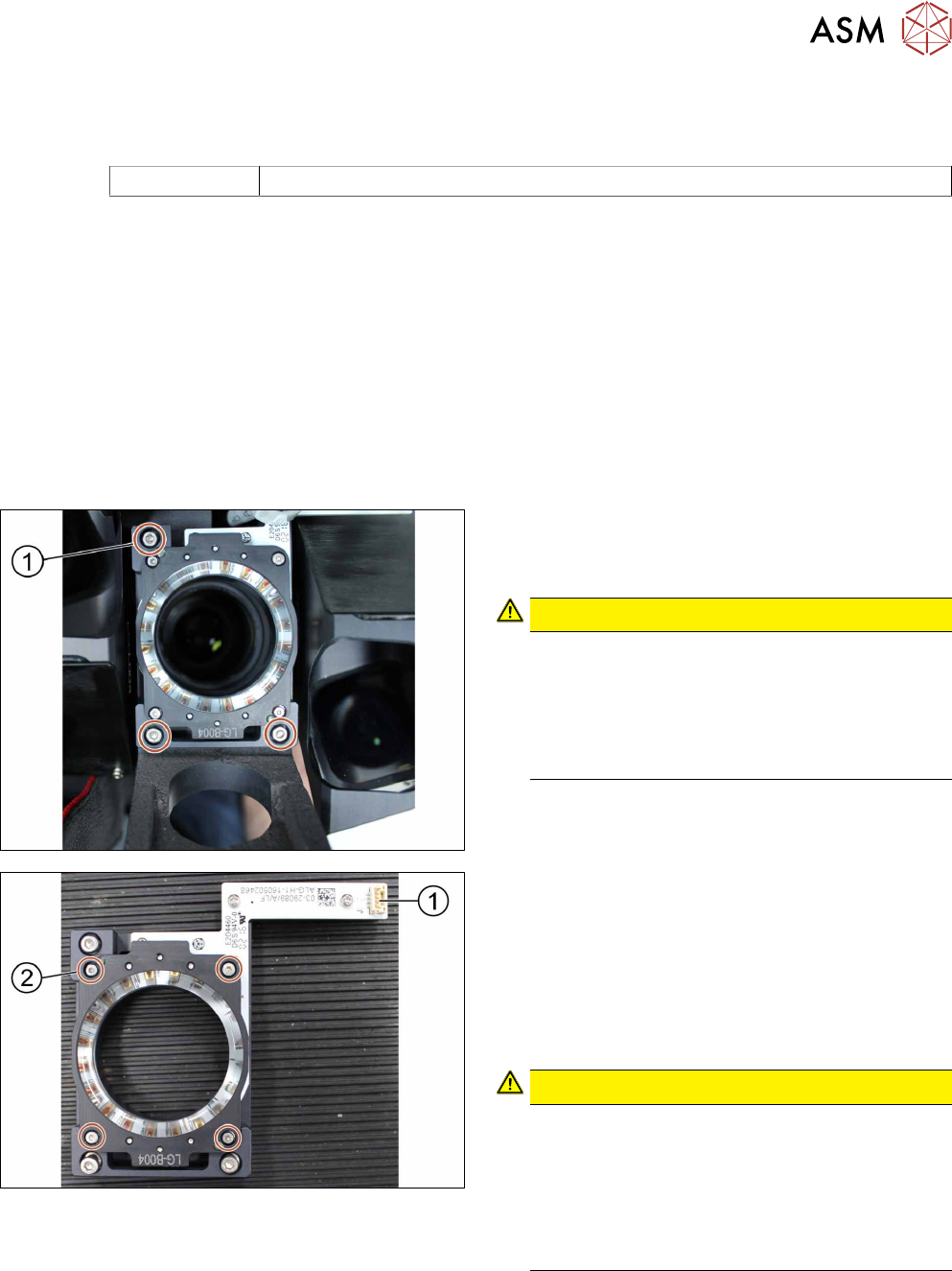
Removal
► Unplug the connector
► Unscrew the three screws (1) using an Allen key
size 2.5.
CAUTION!
Small screws
The screws are very small. When the screws fall
into the machine they may damage it.
Make sure the screws don’t fall into the machine.
Make sure no screw is left behind inside the
machine.
.
1. Connector
2. Screw (4 x) and washers (4 x)
► Unscrew and remove the four screws (2) using
an Allen key size 1.5.
► Remove the four washers.
► Separate the high ring light assembly.
CAUTION!
Ring light assembly
The two parts of the ring light assembly are hold
together by two dowel pins. When separating the
two parts the ring light assembly may get dam-
aged.
To separate the two parts, carefully pull the parts
apart.
.