00900194-01_SM_ASM ProcessLens_Dual-lane_EN.pdf - 第17页
3 Replacing spare parts 3.1 Optical head Service Manual ASM ProcessLens Dual-lane 09/2018 17 3 Replacing spare parts 3.1 Optical head 3.1.1 Replacing the optical head Parts 03122959-xx Vision module Equipment and tools ●…

2 General
16 Service Manual ASM ProcessLens Dual-lane 09/2018
3 Replacing spare parts
3.1 Optical head
Service Manual ASM ProcessLens Dual-lane 09/2018 17
3 Replacing spare parts
3.1 Optical head
3.1.1 Replacing the optical head
Parts
03122959-xx Vision module
Equipment and tools
●
Allen key size 2.5
Requirements
●
Machine is switched off.
Removal
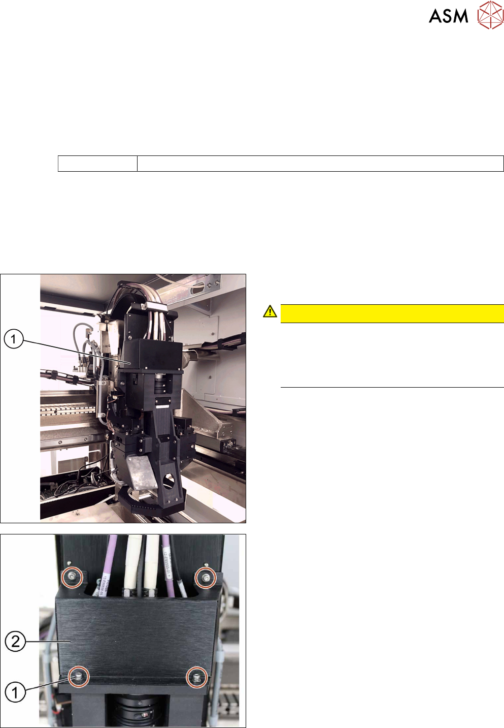
► Move the optical head(1) carefully to the middle
of the machine.
CAUTION!
Sensitive camera system
The camera system is very sensitive and must
therefore not be touched.
Make sure you don’t touch the camera when
moving the gantry.
.
► Remove the cover(2) that protects the connec-
tion spots for the cables by unscrewing the
screws(1) by using an Allen key size 2.5.
► Place the dismantled cover on a service table.
3 Replacing spare parts
3.1 Optical head
18 Service Manual ASM ProcessLens Dual-lane 09/2018
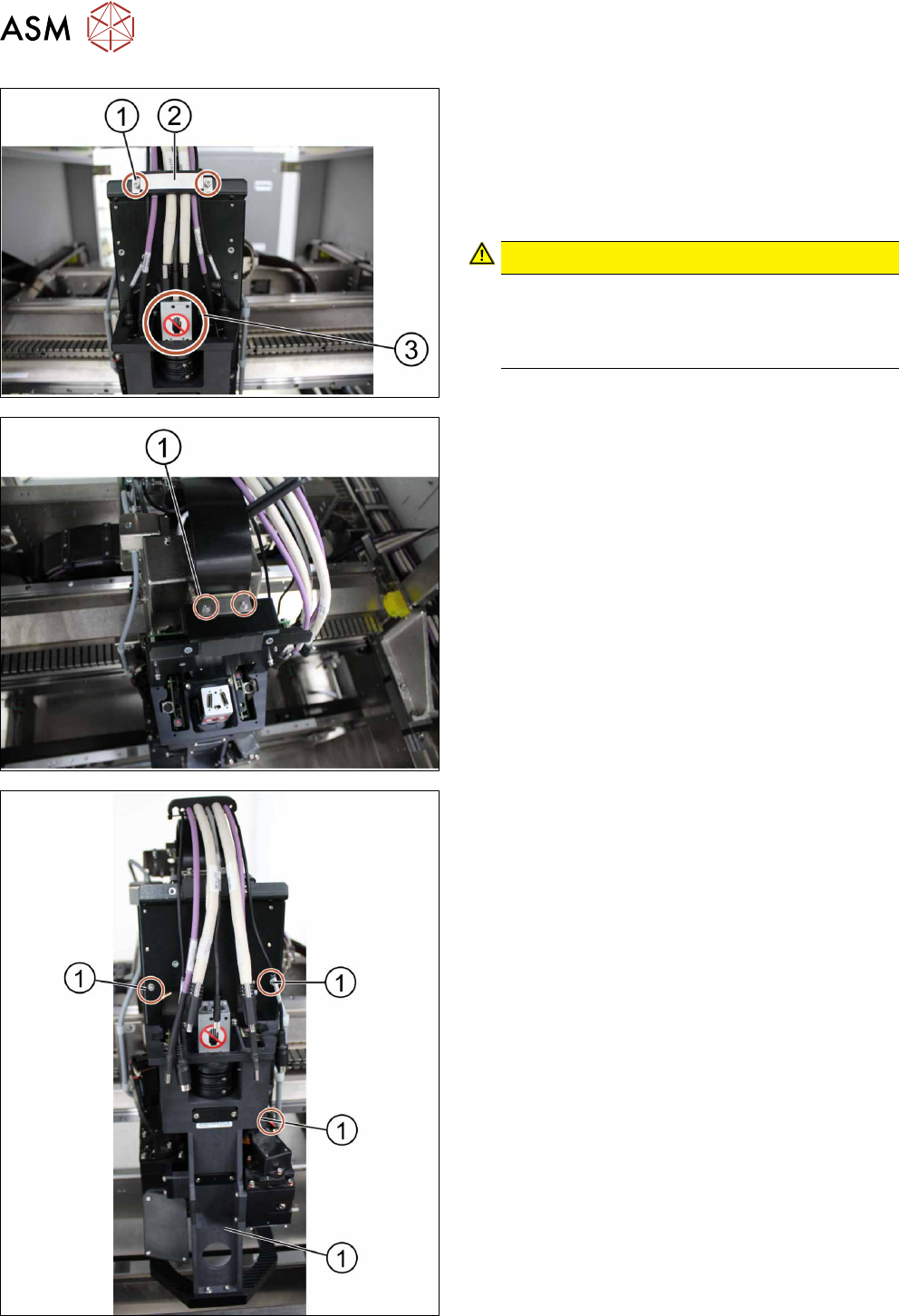
► Remove the cable clamp(2) that fixes the cables
by unscrewing the screws(1) using an Allen key
size 2.5.
► Place the dismantled cable clamp(2) on a ser-
vice table.
► Unplug the cables.
CAUTION!
Sensitive camera system
The camera system (3) is very sensitive.
Therefore do not touch the camera system to
avoid damage to it.
.
► Carefully put the cables aside.
► Unscrew and remove the two screws(1) moun-
ted on top of the optical head fixing the ribbon
cable connectors using an Allen key size 2.5.
► Remove the ribbon cable connectors out of the
sockets by pulling the clamps apart.
► Unscrew the screws(1) fixing the optical head at
the machine using an Allen key size 2.5. Start
from the bottom.
► Carefully unscrew all screws. Make sure you
don’t drop the optical head.