00900194-01_SM_ASM ProcessLens_Dual-lane_EN.pdf - 第24页
3 Replacing spare parts 3.2 DLP 24 Service Manual ASM ProcessLens Dual-lane 09/2018 3.2 DLP 3.2.1 Replacing the DLP left and right controller Parts Fig.3: Right DLP module (1) 03139342-xx In-house left DLP module 031393…
3 Replacing spare parts
3.1 Optical head
Service Manual ASM ProcessLens Dual-lane 09/2018 23
3.1.4 Checking the function of the low ring light and the high ring light
Requirements
●
Machine is switched on.
●
Machine doors are open.
●
The low ring light and the high ring light are mounted.
Checking the function
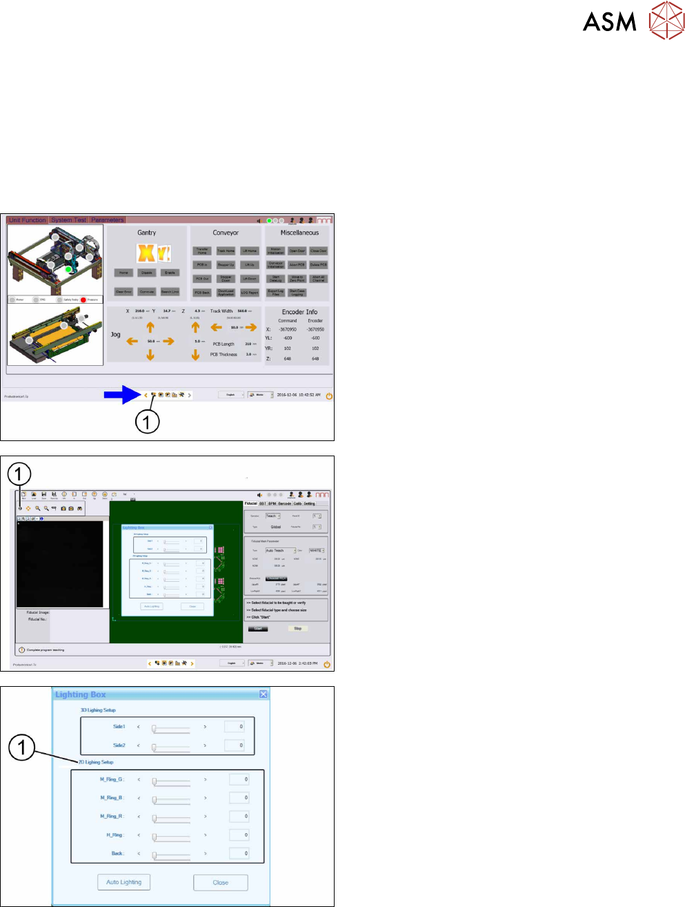
► Go to the diagnostic pages and press the control
button(1).
► On the Lighting control page click on the light-
ing control button(1).
► The Lighting box dialog is displayed.
► In the 2D Lighting Setup section(1) push the
slider to the right.
► Starting with slider bar M-Ring_G check the
green light of the low ring light.
► Check if all LEDs are functional and flashing by
using a mirror or view from underneath the op-
tical head.
► Approach the same for all other slider bars in that
section.
3 Replacing spare parts
3.2 DLP
24 Service Manual ASM ProcessLens Dual-lane 09/2018
3.2 DLP
3.2.1 Replacing the DLP left and right controller
Parts
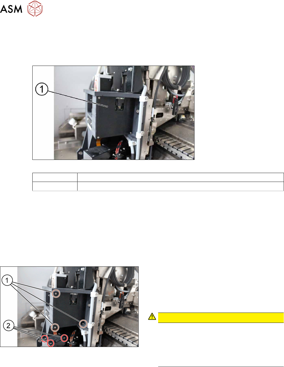
Fig.3: Right DLP module (1)
03139342-xx In-house left DLP module
03139345-xx In-house right DLP module
Equipment and tools
●
Allen key size 1.5
●
Allen key size 2.0
●
Philips screwdriver
Requirements
●
Machine is switched off.
Removal
► Unscrew and remove the three screws(1) using
a Philips screwdriver to remove the cover of the
DLP module (circuit board).
► Unscrew and remove the three screws(2) using
a Philips screwdriver to remove the cover of the
DMD module (connector).
CAUTION!
Small screws
The screws are very small. When the screws fall
into the machine they may damage it.
Make sure the screws don’t fall into the machine.
Make sure no screw is left behind inside the
machine.
.
3 Replacing spare parts
3.2 DLP
Service Manual ASM ProcessLens Dual-lane 09/2018 25
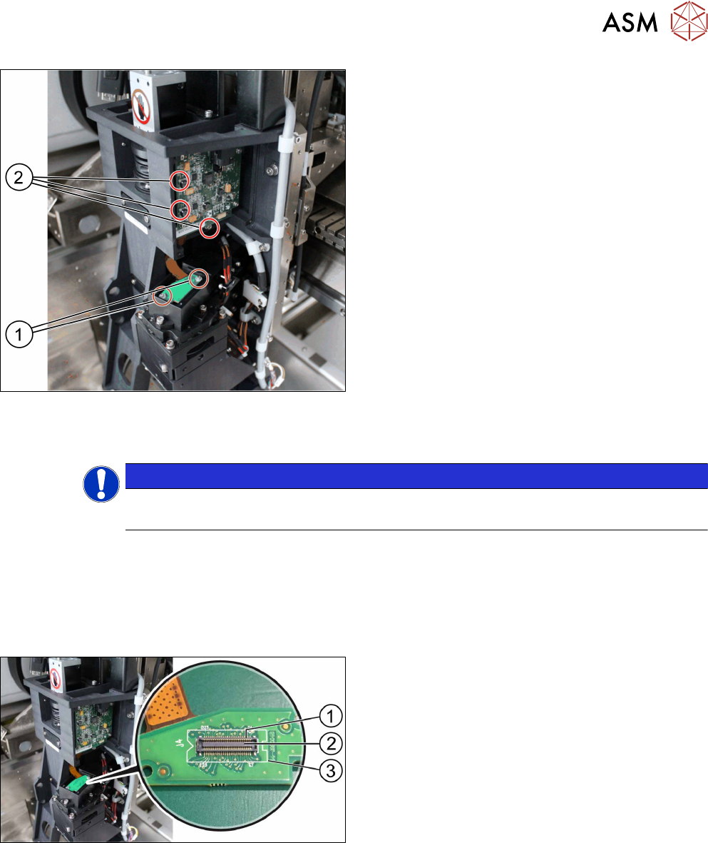
► Unscrew and remove the two screws(1) that
connect the connector with the DMD module by
using an Allen key size 1.5.
► Carefully lift the connector of DMD module.
► Unscrew and remove the three screws(2) of the
DLP module by using an Allen key size 2.0.
► Remove the circuit board and replace it.
► The steps for the left and the right module are
identical.
Installation
Follow the removal instructions in reverse order for installation.
NOTICE
Modules are not interchangeable
Be aware that the two modules are not interchangeable.
3.2.2 Checking the DLP module
Requirements
●
DLP module is dismantled.
Checking the module
► Put the DLP module in its position.
► On the DLP interface board to the DMD(3) make
sure that the connector(2) is in the right position
and does not bend the pin(1). Use an external
light to check that the holes of the connector and
the drilling holes for the screws are in line.
► If the connector and the pin are in line a notice-
able click sound can be heard when the con-
nector is pressed down.