00900194-01_SM_ASM ProcessLens_Dual-lane_EN.pdf - 第93页
4 Replacing spare parts at the conveyor 4.7 Boards Service Manual ASM ProcessLens Dual-lane 09/2018 93 4.7 Boards 4.7.1 Replacing the conveyor control TSP420 Parts Fig.79: Conveyor control TSP420 03087642-xx Conveyor co…
4 Replacing spare parts at the conveyor
4.6 Fiber optic cables and laser light barriers
92 Service Manual ASM ProcessLens Dual-lane 09/2018
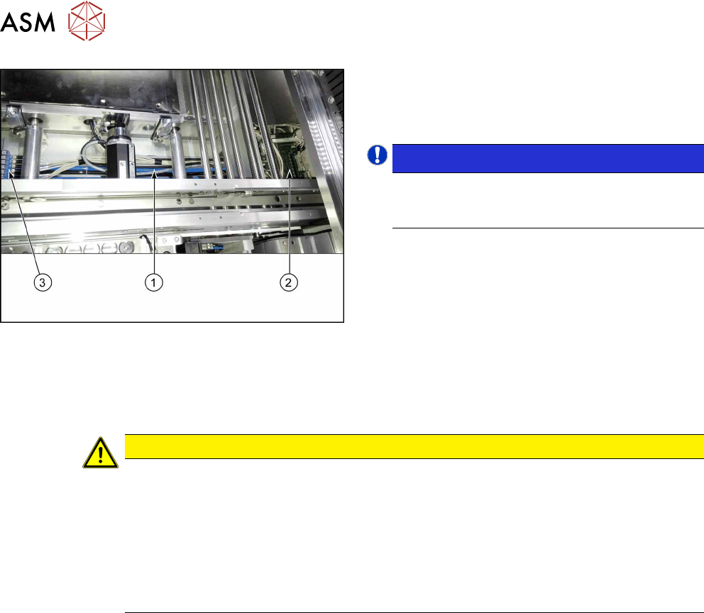
Fig.78: Cables
The cables are run through the conveyor rails, the
hoses on the base(1) of the conveyor to the conveyor
control(2), the fiber optic cables are run to the fiber
optic sensors(3).
NOTICE!
Hoses
One hose (black or blue) always contains all the
cables / fiber optic cables for one conveyor rail.
.
► Carefully unthread the cables / fiber optical
cables.
Remove any cable ties.
Installation
► Follow the removal instructions in reverse order for installation. Also observe the following
instructions:
CAUTION
Installation instructions
► Fiber optical cable: Check the settings for the transmitter / receiver and correct these if
necessary (see 4.6.4.1 "Setting the fiber optic sensor" [}85]).
► For an overview of the connectors, switches etc. of the TSP420, refer to section
4.7.1.1 "Conveyor control TSP420 [03087642-xx]" [}94].
► Replace any open cable ties.
Make sure that the cable ties and the heads of the cable ties do not rub against any
parts when you do this.
4 Replacing spare parts at the conveyor
4.7 Boards
Service Manual ASM ProcessLens Dual-lane 09/2018 93
4.7 Boards
4.7.1 Replacing the conveyor control TSP420
Parts
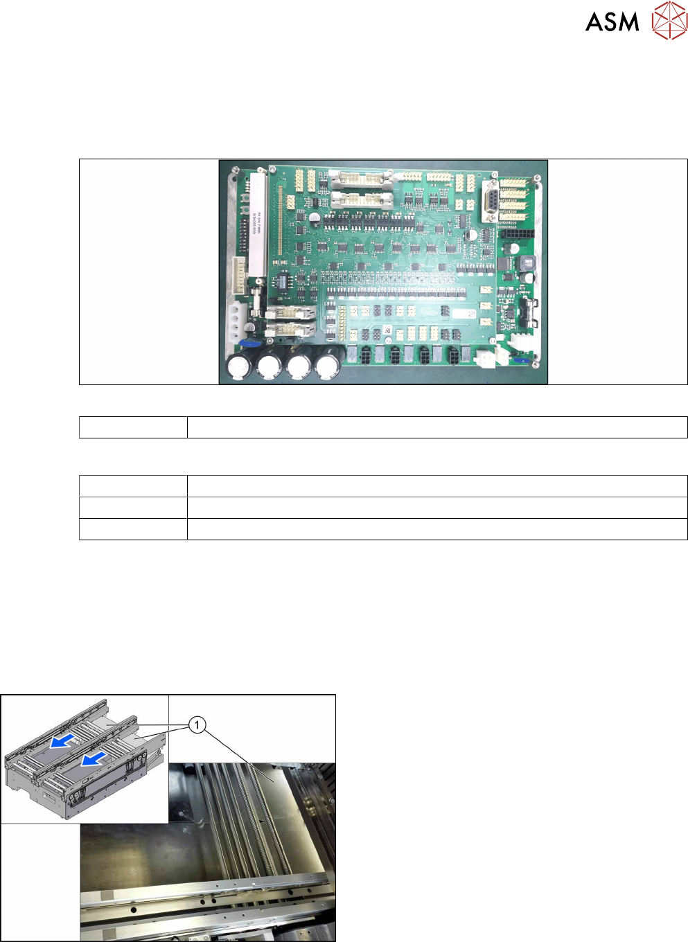
Fig.79: Conveyor control TSP420
03087642-xx Conveyor control TSP420 complete
Equipment and tools
00096290-xx Fork wrench set
Side cutter
Cable tie
Removal
► Use the software or manually move the conveyor rail into a position which allows you best
access.
– To move the conveyor rail manually, pull the toothed belt of the width adjustment unit.
► Switch off the machine, disconnect it from the power supply and secure it to prevent
unauthorized reactivation.
► Move the gantry out of the transport area as far as possible to one side of the machine.
Fig.80: Covers
► Remove the spacer bolts fastening the cover(1)
above the conveyor control and remove the
cover.
► Unplug all electrical connections to the conveyor control. If necessary, mark their positions to
make clear assignment easier later on.
4 Replacing spare parts at the conveyor
4.7 Boards
94 Service Manual ASM ProcessLens Dual-lane 09/2018
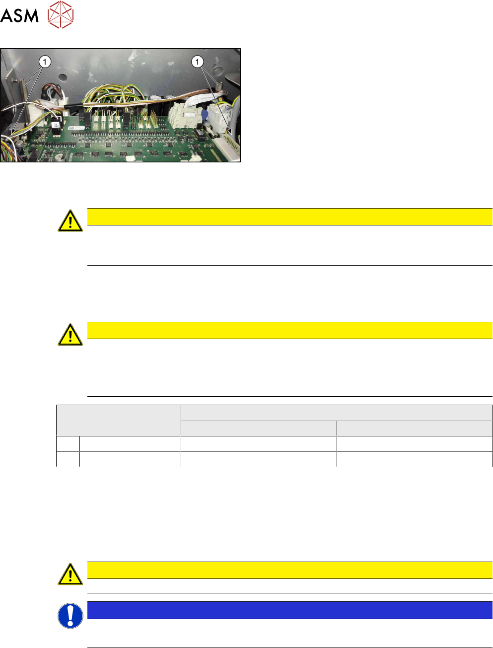
Fig.81: Spacer bolts
► Loosen the four spacer bolts(1).
► Remove the conveyor control together with the mounting plate from the machine.
CAUTION
Do not remove the conveyor control from the mounting plate.
The conveyor control may not be removed from the mounting plate because the mounting
plate serves as a cooling element for the conveyor control.
Installation
► Follow the removal instructions in reverse order for installation. Also observe the following
instructions:
CAUTION
Installation instructions
► Perform a download if needed (see LINK).
► Check the jumper setting: jumper 1 and 2 must be set correctly for both TSP420 (see
table).
Jumper Dip switch setting
Lane 1 Lane 2
1 For MCAN 2-3 2-3
2 For internal CAN 1-2 1-2
4.7.1.1 Conveyor control TSP420 [03087642-xx]
Two TSP420 are fitted in SIPLACE TX-Series machines.
The conveyor control "TSP420 assembly" [03087642-xx] comprises the following components:
●
Main board: TSP420-M [ 03087640-xx ]
●
I/O board: TSP420-IO [ 03087641-xx ]
CAUTION
These two boards may not be separated!
NOTICE
Terminating resistor (cable set PCB dual conveyor [03110653‑xx])
The terminating resistor is set for the "Shuttle Option" by default.