MAN00000772_SI-G200BB_SVCPDFA.pdf - 第103页
Install Tray Unit (Including machine modification) SHEET 64/73 WKGB-10104-03 Installing Tray Unit (Including machine modification) [Setup of VU, VL axis p art s replacement st andby height] 1 Return the unit to the origi…
Install Tray Unit (Including machine modification)
SHEET
63/73
WKGB-10104-03
Installing Tray Unit
(Including machine modification)
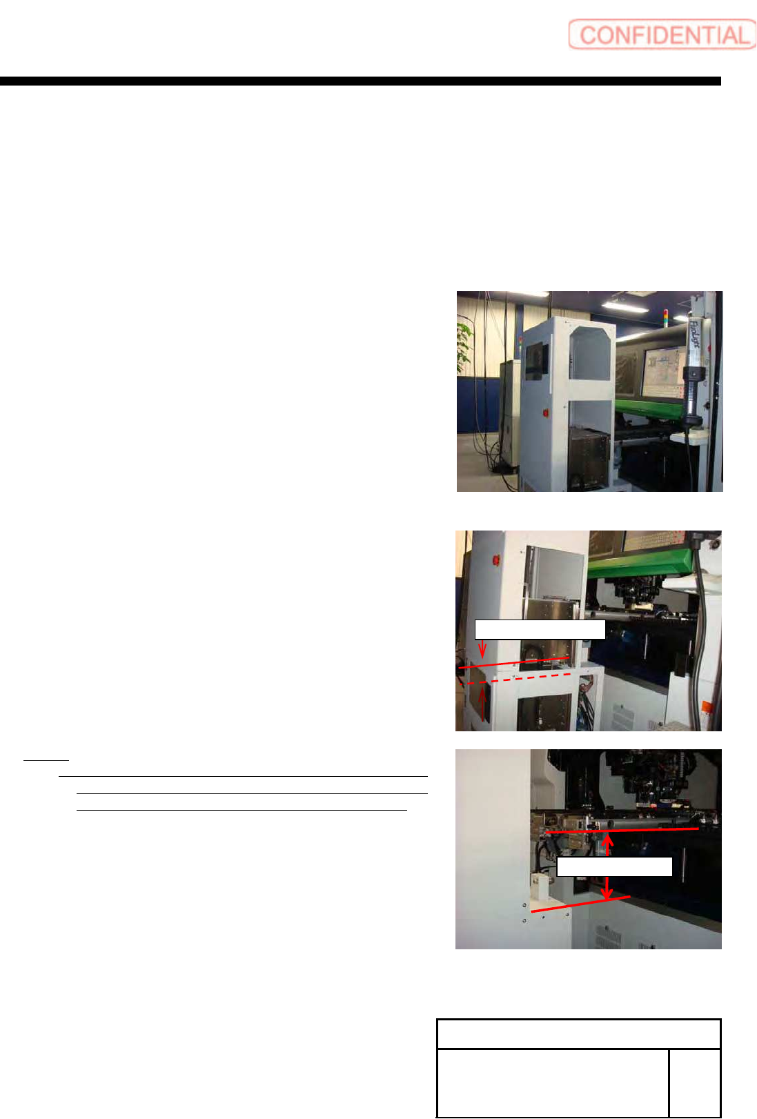
[Checking VU, VL closest reaching distance]
1 Return the unit to the origin.
2 Move the VU axis to the Z501 by manual V
axis operation.
3 Open the tray unit side cover.
4 Check that interval between the VU rack and
the VL rack is 41[mm] or more.
NOTE:
If this clearance is less than 41[mm], the relation of the
height between mounter and tray unit might be wrong.
In this case please set up again this height relation.
5 Install the removed side cover to the
previous state.
41[mm] or more
204±2[mm]
Install Tray Unit (Including machine modification)
SHEET
64/73
WKGB-10104-03
Installing Tray Unit
(Including machine modification)
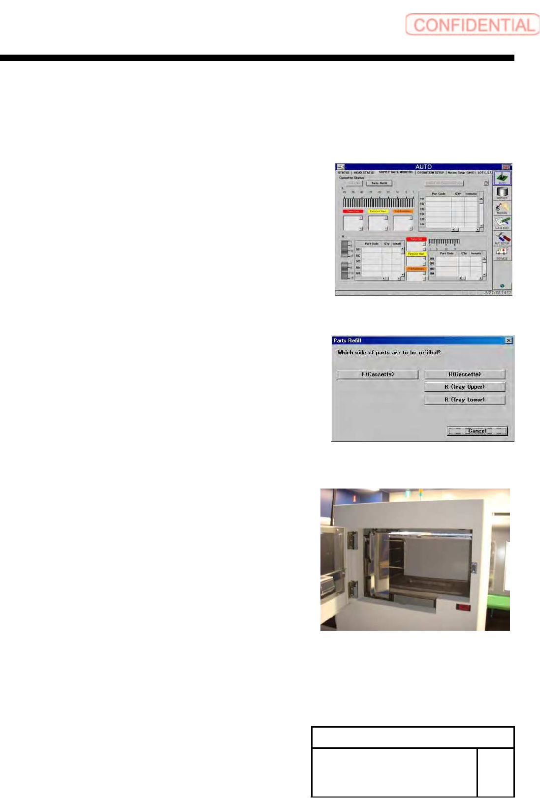
[Setup of VU, VL axis parts replacement standby height]
1 Return the unit to the origin.
2 Press the Parts replace button on the
AUTO/PARTS SUPPLY STATUS screen.
3 Select the R (Tray upper) button.
4 Open the tray upper door.
Install Tray Unit (Including machine modification)
SHEET
65/73
WKGB-10104-03
Installing Tray Unit
(Including machine modification)
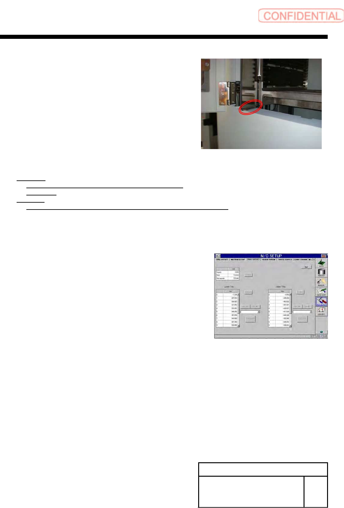
5 Check clearance between the tray inside
door and the tray cover.
6 Calculate the standby height.
Equation:
Parts replace standby height
= 1.0[mm] –
Clearance
Example:
Parts replace standby height
= 1.0[mm] – 3.0[mm] =-2.0[mm]
7 Close the door of the tray.
8 Display the M/C SETUP/tray Offset screen.
9 Input the calculated standby height into the O on
the upper tray.
10 Press the Set button to reflect the Setup.
11 Again, perform parts replacement on the R
(Tray upper) to check that the door is
completely opened.
12 Set the standby height of the lower tray by
the same procedure.