MAN00000772_SI-G200BB_SVCPDFA.pdf - 第627页
4. Basic Operations of the Multifunctional Mounter TFGB-10101-0 1 SI-G200 (B Head) Overview SHEET 12/20 4-5 Mounting The H axis des cends above t he mounting p osition, an d picked up pa rts are m ounted onto a P WB. [Ac…
4. Basic Operations of the Multifunctional Mounter
TFGB-10101-01
SI-G200 (B Head) Overview
SHEET
11/20
- Mounting of globally recognized parts in a recovery path
In a recovery path, globally recognized parts are forcibly switched to individually recognized ones, and
operations set in motion data are performed for them.
- When multiple part types based on shapes exist in one path, downloading machine model data causes a
warning message to appear.
<Points to Note>
- Concerning part data in which Gull-wing and J-lead coexist, the shape of a lead group at the top is
applied.
- Creation and editing of parts for global recognition with recognition data editing software used is
conducted with individual recognition used.
- Recognition check in automatic production, operating conditions, and teaching is conducted with global
recognition used.
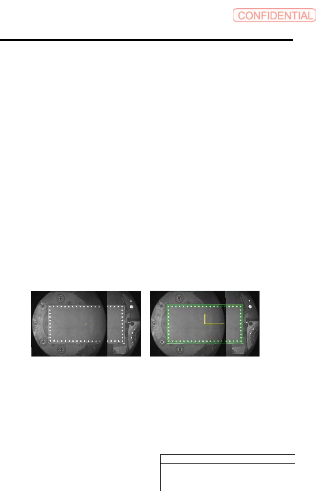
4-4-3 Split Recognition
Split recognition can be conducted for lead parts, BGA parts, odd-shaped parts (with leads), and
odd-shaped parts (without leads).
<Points to Note>
When the fixed camera (Large view) is used, there is a circular portion that is not imaged (portion where
lighting is unstable) at both ends of a split image. Therefore, part recognition data cannot be created
automatically. In this case, manual creation of part recognition data and recognition test need to be
repeated.
Left: Result of Composition of Split Images of a Virtual Part (100 x 50 mm),
Right: Result of Recognition
4. Basic Operations of the Multifunctional Mounter
TFGB-10101-01
SI-G200 (B Head) Overview
SHEET
12/20
4-5 Mounting
The H axis descends above the mounting position, and picked up parts are mounted onto a PWB.
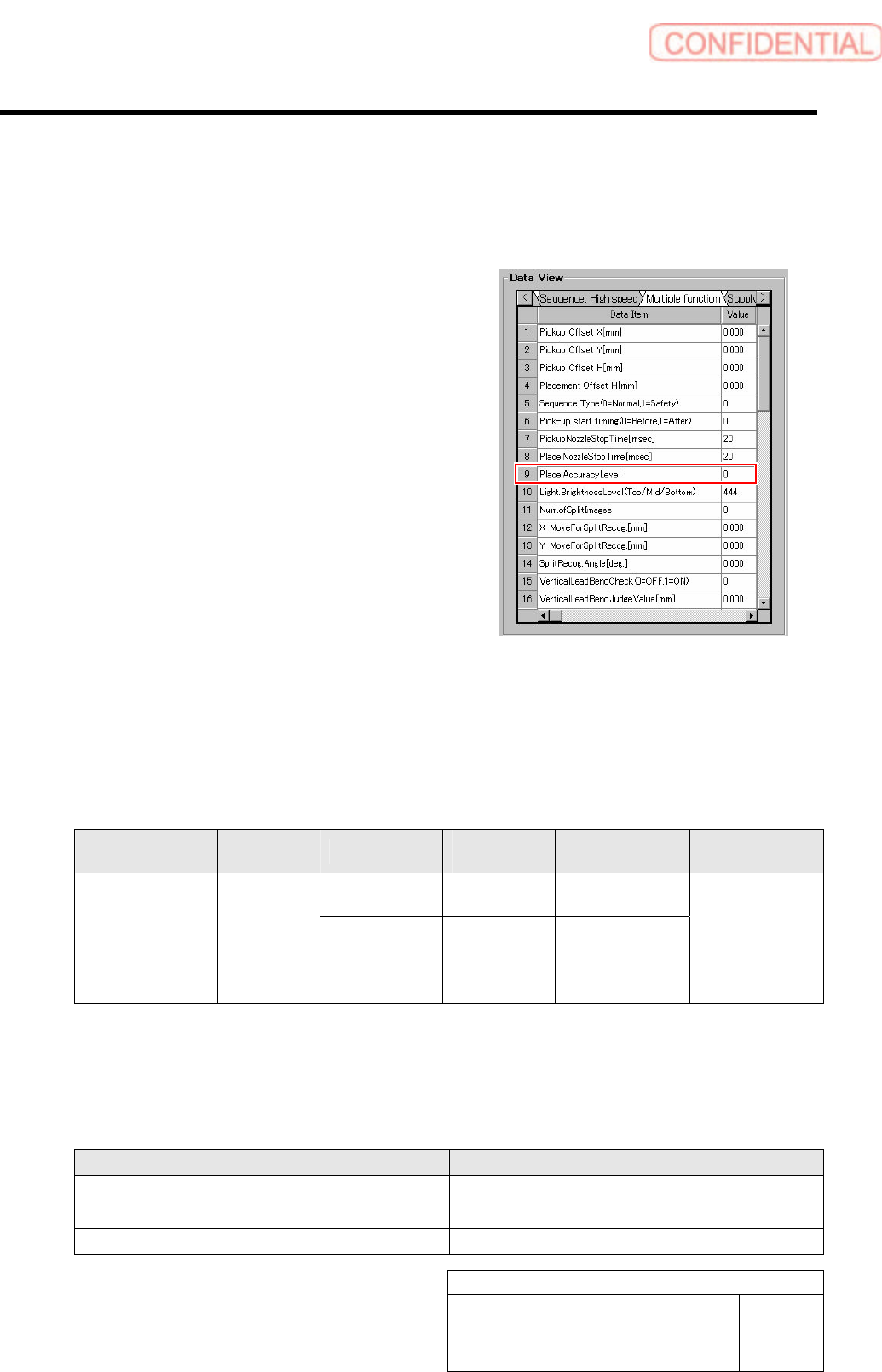
[Accuracy level]
There are two types for the Accuracy level: normal
mode and high-Accuracy mode. For parts that need
higher positioning Accuracy when they are mounted,
the high-Accuracy mode is selected. The Accuracy
level is defined in part data, and it can be set in
“Sequence (Multifunction)” displayed after “Data
Editing” and “Part Management” have been selected in
this order.
Depending on the setting for the Accuracy level, the recognition angle, recognition method, and mounting
operation differ. In the normal mode, parts are recognized with the recognition angle being 0 degree, and
they are mounted continuously. In the high-Accuracy mode, in order to improve the mounting Accuracy,
each of the parts is recognized with an angle suitable for mounting it and then mounted.
Difference in Pickup, Antibacklash, Recognition Angle, Recognition Method, and Mounting
Operation, Depending on the Accuracy Level
Accuracy Level Pickup Antibacklash
Recognition
Angle
Recognition
Method
Mounting
Operation
Disable 0 degree
Global/Individual
Split
0
(normal mode)
Continuous
pickup
Enable 0 degree Individual/split
Continuous
mounting
1
(high-Accuracy mode)
Continuous
pickup
Enable Mounting angle Individual/split
Each of parts is
recognized and
mounted.
When parts whose Accuracy level is the normal mode fall under one of the items below, an antibacklash
operation is performed forcibly for them. The anti-backlash motion for the global recognition parts is not
executed.
Antibacklash Operating Conditions for Parts in the Normal Mode
Item Condition
Part thickness 3.00 mm or more
Maximum number of leads (in one direction) One or more
Total number of balls (BGA/odd-shaped parts (with balls)) Four balls or more
4. Basic Operations of the Multifunctional Mounter
TFGB-10101-01
SI-G200 (B Head) Overview
SHEET
13/20
<Points to Note>
- When parts in the normal mode and ones in the high-Accuracy mode coexist in one path during part
pickup, parts with the same Accuracy level as that of the first parts to be picked up are picked up first
and then mounted. The remaining parts are passed on to a recovery path. In addition, when machine
model data is downloaded, a warning message appears.
Pickup and Mounting Operation When Parts in One Mode
and Ones in the Other Coexist in One Path
Accuracy Level of the First Parts to Be
Picked Up
Pickup and Mounting Operation
Normal mode
Only parts in the normal mode (including globally recognized parts) are picked up.
(The remaining parts are passed on to a recovery path.)
High-Accuracy mode
Only parts in the high-Accuracy mode are picked up.
(The remaining parts are passed on to a recovery path.)
In these cases, DAS needs to be operated so that parts in one mode and ones in the other do not coexist in
one path.
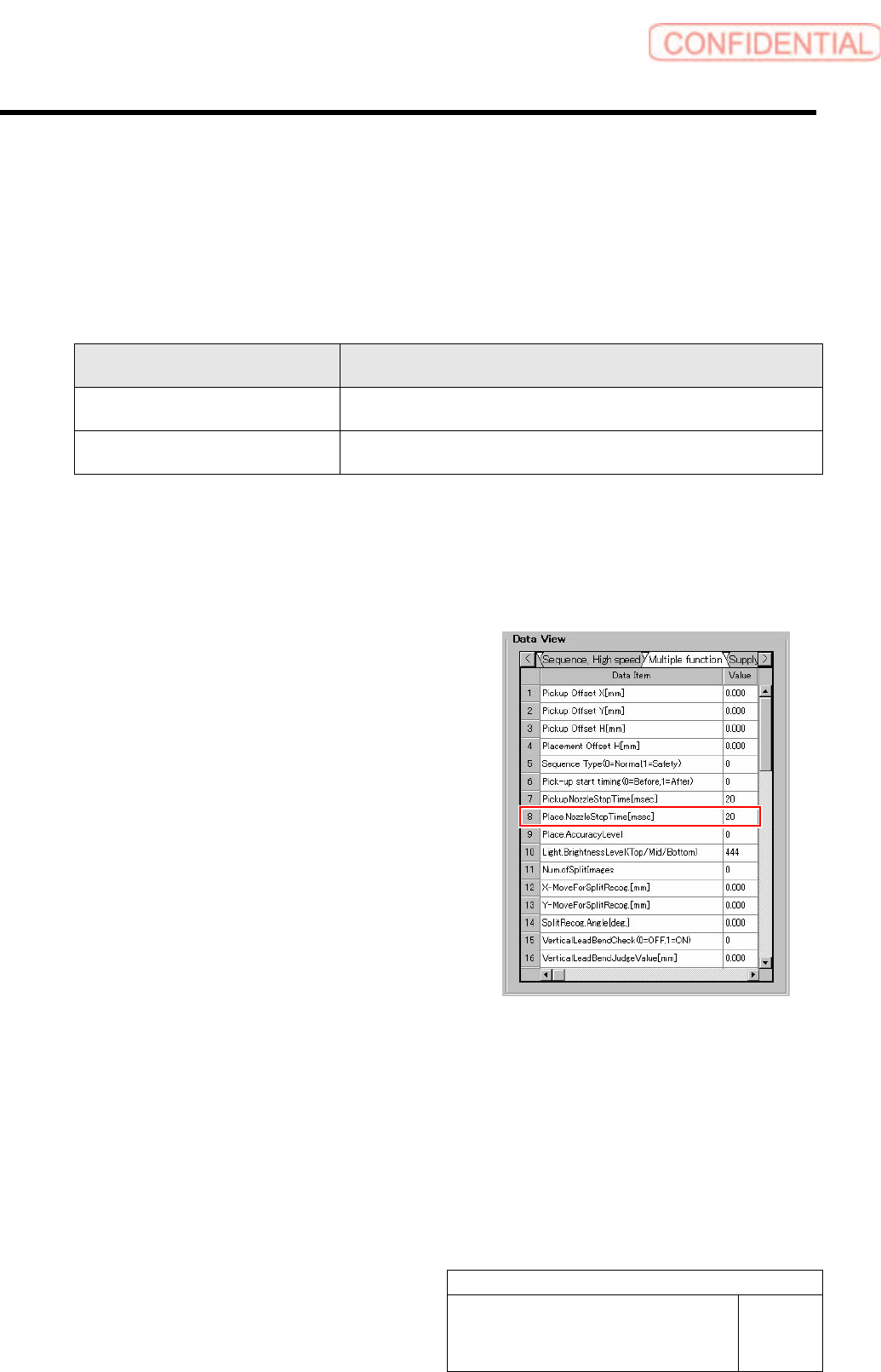
[Place Nozzle Stop Time]
Because the multifunctional mounter handles larger-size
parts that the high-speed one cannot, the stationary time of
the former is as follows:
When override is 60% or less:
Values input in part data are used.
When override is 61% or more:
-10 x (overall override: 1.0 to 0.01) + 13 msec
* Override means H axis override x overall override.