MAN00000772_SI-G200BB_SVCPDFA.pdf - 第593页
Alarm List for the Servo Pack "S igma-III" Series (SGDS type) BBGB-10101-01 Alarm List for the Servo Pack "Sigma-III" Series (SGDS type) SHEET 4/18 Alarm Display Alarm Name Situation at Alarm Occurren…
Alarm List for the Servo Pack "Sigma-III" Series (SGDS type)
BBGB-10101-01
Alarm List for the Servo Pack
"Sigma-III" Series (SGDS type)
SHEET
3/18
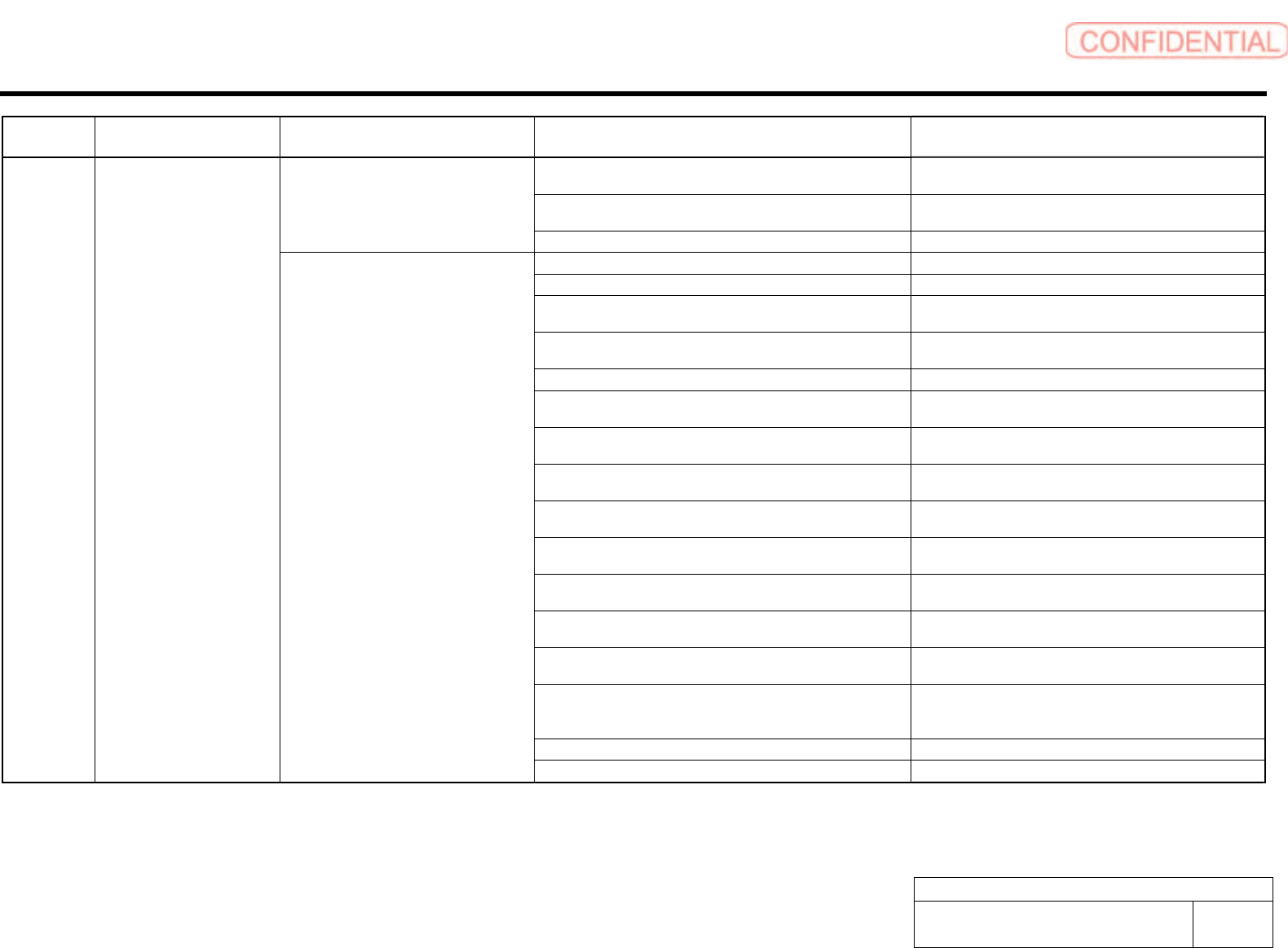
Alarm
Display
Alarm Name Situation at Alarm Occurrence Cause Corrective Actions
The overload alarm has been reset by turning OFF the power
too many times.
Change the method to reset the alarm.
The connection is faulty between the SERVOPACK board and
the thermostat switch.
Replace the SERVOPACK.
Occurred when the control power supply
was turned ON.
The SERVOPACK board fault occurred. Replace the SERVOPACK.
The connection between grounding and U, V, or W is incorrect. Check and then correct the wiring.
The grounding line has contact with other terminals. Check and then correct the wiring.
A short circuit occurred between the grounding and U, V, or W
of the servomotor cable.
Repair or replace the servomotor cable.
A short circuit occurred between phase U, V, or W of the
servomotor.
Repair or replace the servomotor cable.
The wiring of the regenerative resistor is incorrect. Check and then correct the wiring.
A short circuit occurred between the grounding and U, V, or W
of the SERVOPACK.
Replace the SERVOPACK.
A SERVOPACK fault occurred (current feedback circuit, power
transistor or board fault).
Replace the SERVOPACK.
A short circuit occurred between the grounding and U, V, W of
the servomotor.
Replace the servomotor.
A short circuit occurred between the grounding and U, V, W of
the servomotor.
Replace the servomotor.
A fault occurred in the dynamic brake circuit. Replace the SERVOPACK, and reduce the load, or reduce
the number of rotations used.
The dynamic brake was activated too frequently, so a DB
overload alarm occurred.
Replace the SERVOPACK, and reduce the DB operation
frequency.
The overload alarm has been reset by turning OFF the power
too many times.
Change the method to reset the alarm.
The overload or regenerative power exceeds the regenerative
resistor's capacity.
Reconsider the load and operation conditions.
The direction or the distance of the SERVOPACK to other
devices is incorrect.
Heat radiation of the panel or heat around the panel occurred.
The ambient temperature for the SERVOPACK must be
55-degrees centigrade or less.
A SERVOPACK fan fault occurred. Replace the SERVOPACK.
A.100 Overcurrent
(Heat Sink Overheated)
Occurred when the main circuit power
supply was turned ON or when an
overcurrent occurred while the servomotor
was running.
A SERVOPACK fault occurred. Replace the SERVOPACK.
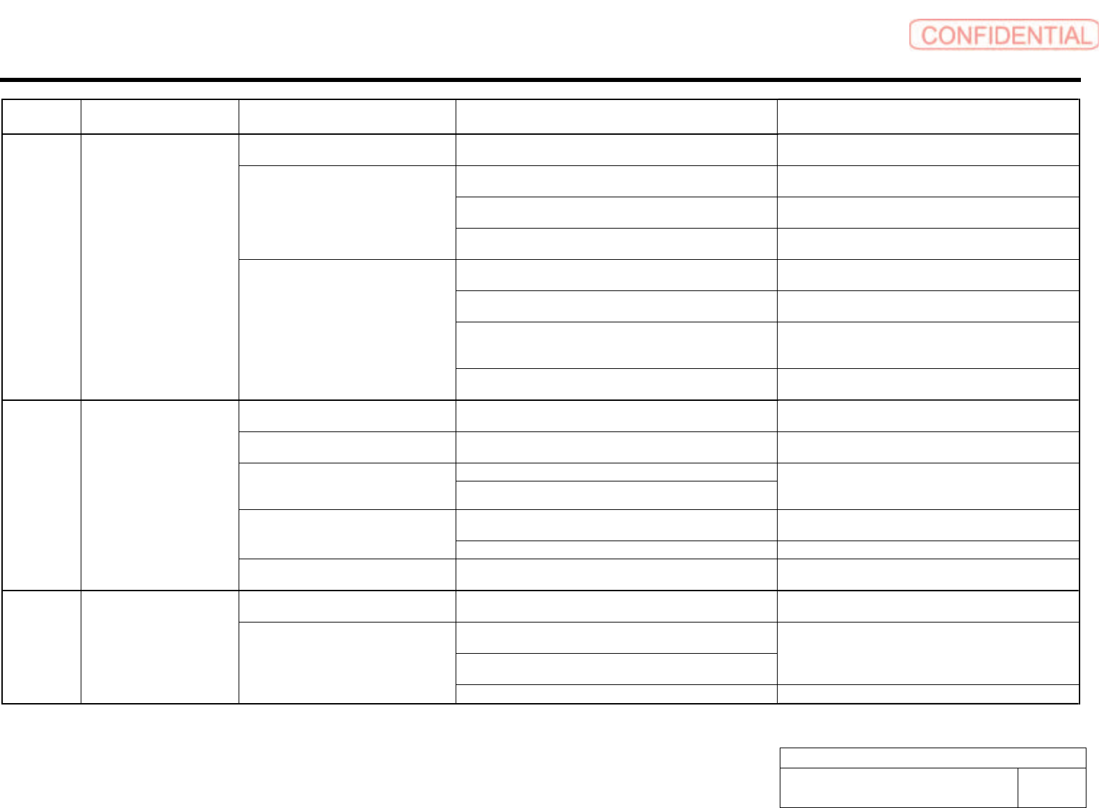
Alarm List for the Servo Pack "Sigma-III" Series (SGDS type)
BBGB-10101-01
Alarm List for the Servo Pack
"Sigma-III" Series (SGDS type)
SHEET
4/18
Alarm
Display
Alarm Name Situation at Alarm Occurrence Cause Corrective Actions
Occurred when the control power supply
was turned ON.
A SERVOPACK board fault occurred. Replace the SERVOPACK.
Pn600 is set to a value other than "0" for a servomotor of 400 W
or less, and an external regenerative resistor is not connected.
Connect an external regenerative resistor, or set Pn600 to
"0" if an external regenerative resistor is not connected.
Check for incorrect wiring or a disconnected wire in the
regenerative resistor.
Correct the wiring for the external regenerative resistor.
Occurred when the main circuit power
supply turned ON.
A SERVOPACK fault occurred, such as regenerative transistor
or a voltage sensor fault.
Replace the SERVOPACK.
Check for incorrect wiring and disconnection of the regenerative
resistor.
Correct the wiring for the external regenerative resistor.
The jumper between B2 and B3 is removed for a servomotor of
500 W or more.
Correct the wiring.
The regenerative resistor is disconnected, so the regenerative
energy became excessive.
Replace the regenerative resistor or replace the
SERVOPACK.
Reconsider the load and operation conditions.
A.300 Regeneration Error Detected
Occurred during normal operation.
A SERVOPACK fault, such as regenerative transistor and
voltage sensor fault, occurred.
Replace the SERVOPACK.
Occurred when the control power supply
was turned ON.
A SERVOPACK board fault occurred. Replace the SERVOPACK.
Occurred when the main circuit power
supply was turned ON.
The power supply voltage is 270 V or more. Correct the input voltage.
The regenerative energy is excessive. Occurred during normal operation (large
increase of regenerative resistor
temperature).
The regenerating state continued.
Select a proper regenerative resistance capacity, or
reconsider the load and operation conditions.
The setting of parameter Pn600 is smaller than the external
regenerative resistor's capacity.
Correct the set value of parameter Pn600. Occurred during normal operation (small
increase of regenerative resistor
temperature).
A SERVOPACK fault occurred. Replace the SERVOPACK.
A.320 Regenerative Overload
Occurred at servomotor deceleration. The regenerative energy is excessive. Select a proper regenerative resistance capacity, or
reconsider the load and operation conditions.
Occurred when the control power supply
was turned ON.
A SERVOPACK board fault occurred. Replace the SERVOPACK.
In the DC power input mode, AC power is supplied through L1
and L2 or L1, L2, and L3.
In the AC power input mode, DC power is supplied through B1/
(+) and (-) terminals.
For AC power input, Pn001.2=0.
For DC power input, Pn001.2=1.
A.330 Main Circuit Wiring Error
Occurred when the main circuit power
supply was turned ON.
Pn600 is set to 0 if the regenerative resistance is disconnected. Set Pn600 to 0.
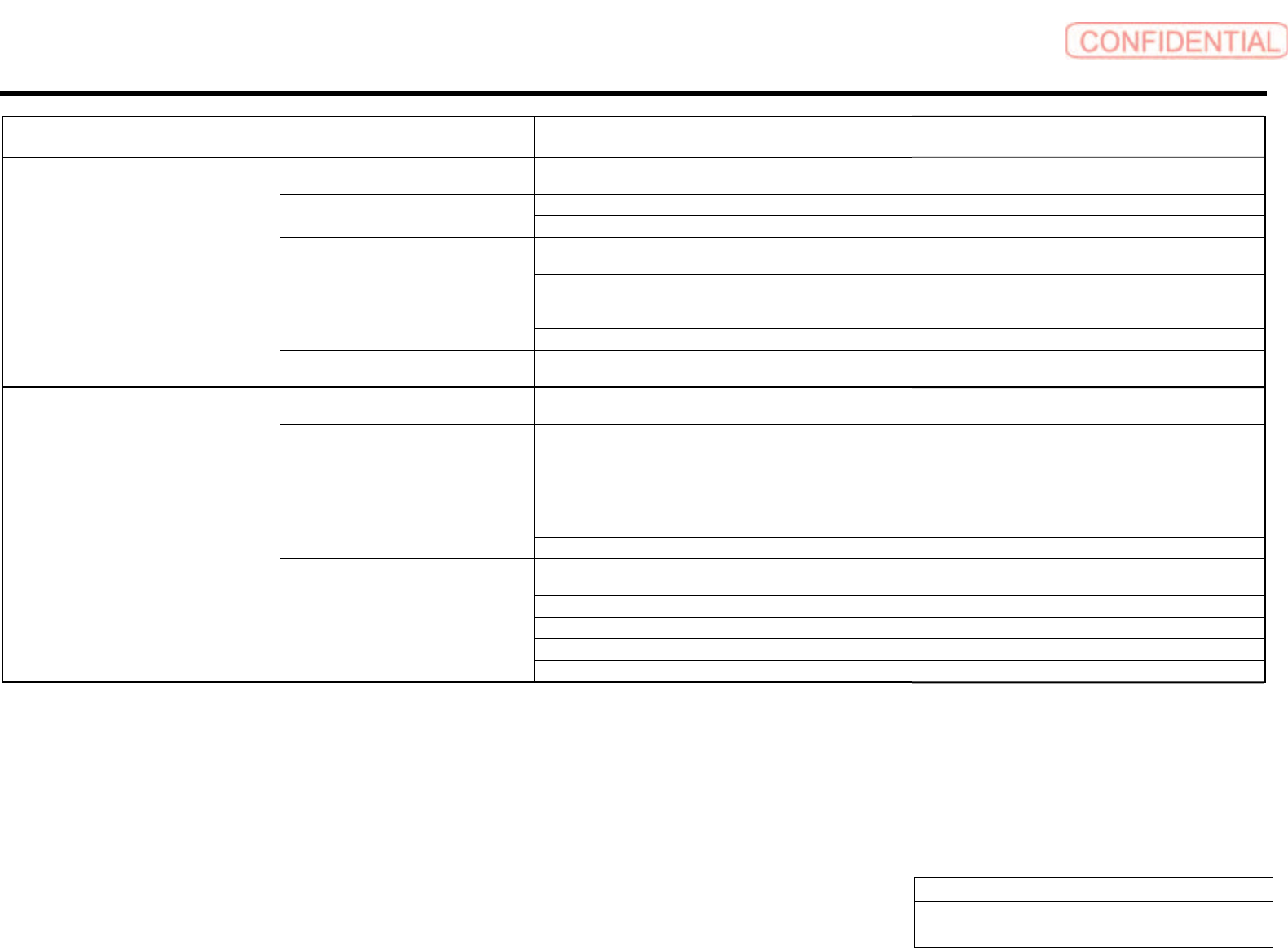
Alarm List for the Servo Pack "Sigma-III" Series (SGDS type)
BBGB-10101-01
Alarm List for the Servo Pack
"Sigma-III" Series (SGDS type)
SHEET
5/18
Alarm
Display
Alarm Name Situation at Alarm Occurrence Cause Corrective Actions
Occurred when the control power supply
was turned ON.
A SERVOPACK board fault occurred. Replace the SERVOPACK.
The AC power voltage is 290 V or more. The AC power voltage must be within the specified range. Occurred when the main circuit power
supply was turned ON.
A SERVOPACK fault occurred. Replace the SERVOPACK.
Check the AC power voltage. (check if there is no excessive
voltage change.)
The AC power voltage must be within the specified range.
The motor speed is high and load moment of inertia is
excessive, resulting in insufficient regenerative capacity.
Check the load moment of inertia and minus load
specifications. Reconsider the load and operation
conditions.
Occurred during normal operation.
A SERVOPACK fault occurred. Replace the SERVOPACK.
A.400 Overvoltage
Occurred at servomotor deceleration. The motor speed is high, and the load moment of inertia is
excessive.
Reconsider the load and operation conditions.
Occurred when the control power supply
was turned ON.
A SERVOPACK board fault occurred. Replace the SERVOPACK.
The AC power supply voltage is 120 V or less. The AC power supply voltage must be within the specified
range.
The fuse of the SERVOPACK is blown out. Replace the SERVOPACK.
The inrush current limit resistor is disconnected, and result in an
abnormal power supply voltage or in an overload of the inrush
current limit resistor.
Replace the SERVOPACK. (Check the power supply
voltage, and reduce the number of times that the main
circuit is turned ON or OFF.)
Occurred when the main circuit power
supply was turned ON.
A SERVOPACK fault occurred. Replace the SERVOPACK.
The AC power supply voltage was lowered, and large voltage
drop occurred.
The AC power supply voltage must be within the specified
range.
A temporary power failure occurred. Clear and reset the alarm, and restart the operation.
The servomotor cable shorts to ground. Repair or replace the servomotor cable.
The servomotor shorts to ground. Replace the servomotor.
A.410 Undervoltage
Occurred during normal operation.
A SERVOPACK fault occurred. Replace the SERVOPACK.