MAN00000772_SI-G200BB_SVCPDFA.pdf - 第690页
Ch ange Procedu re fo r Lever A ssembly o f Head Un it 3. Pull o ut the c o nnector (c am2-U*) of came ra cable , loo sen 2-CP4x 8, and remo v e the de tection c amer a. 4. Lo o sen 2-CP4x 6 f ro m the bac k of th e he a…
Change Procedure for Lever Assembly of Head Unit
Change Procedure for Lever Assembly of Head Unit
[Necessary Jigs]
Dial Gage
Magnet Stand
7mm wrench
[Disassembly]
1 Turn off the main power and air main cock.
2
Open the front slide door.
3 Remove the detection camera Assy.
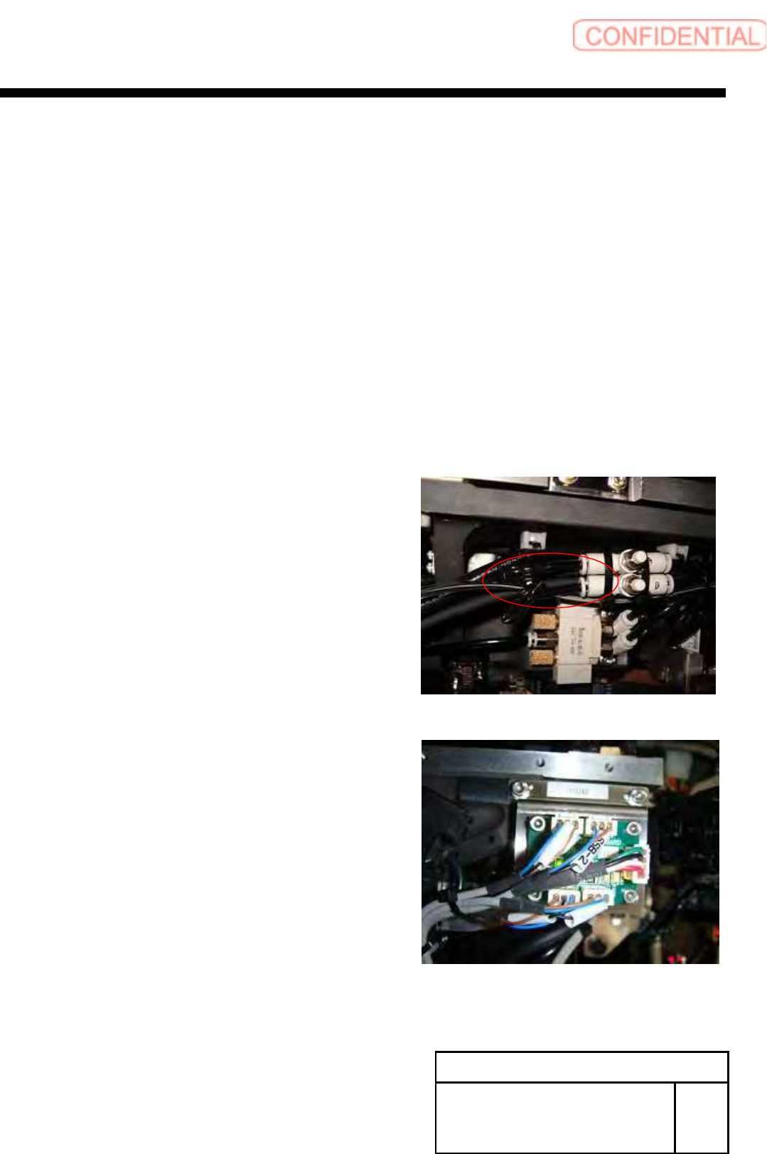
1. Pull out the air tube of rear of HEAD.
2.SSB-2 and SSB-4 connectors pull out from the SSB board at
side of head.
POINT
Cut the cable tie from SSB-2 and SSB-4 cables.
Change Procedure for Head Unit
Lever Assembly
SHEET
1/7
RPGB-11101-1
Change Procedure for Lever Assembly of Head Unit
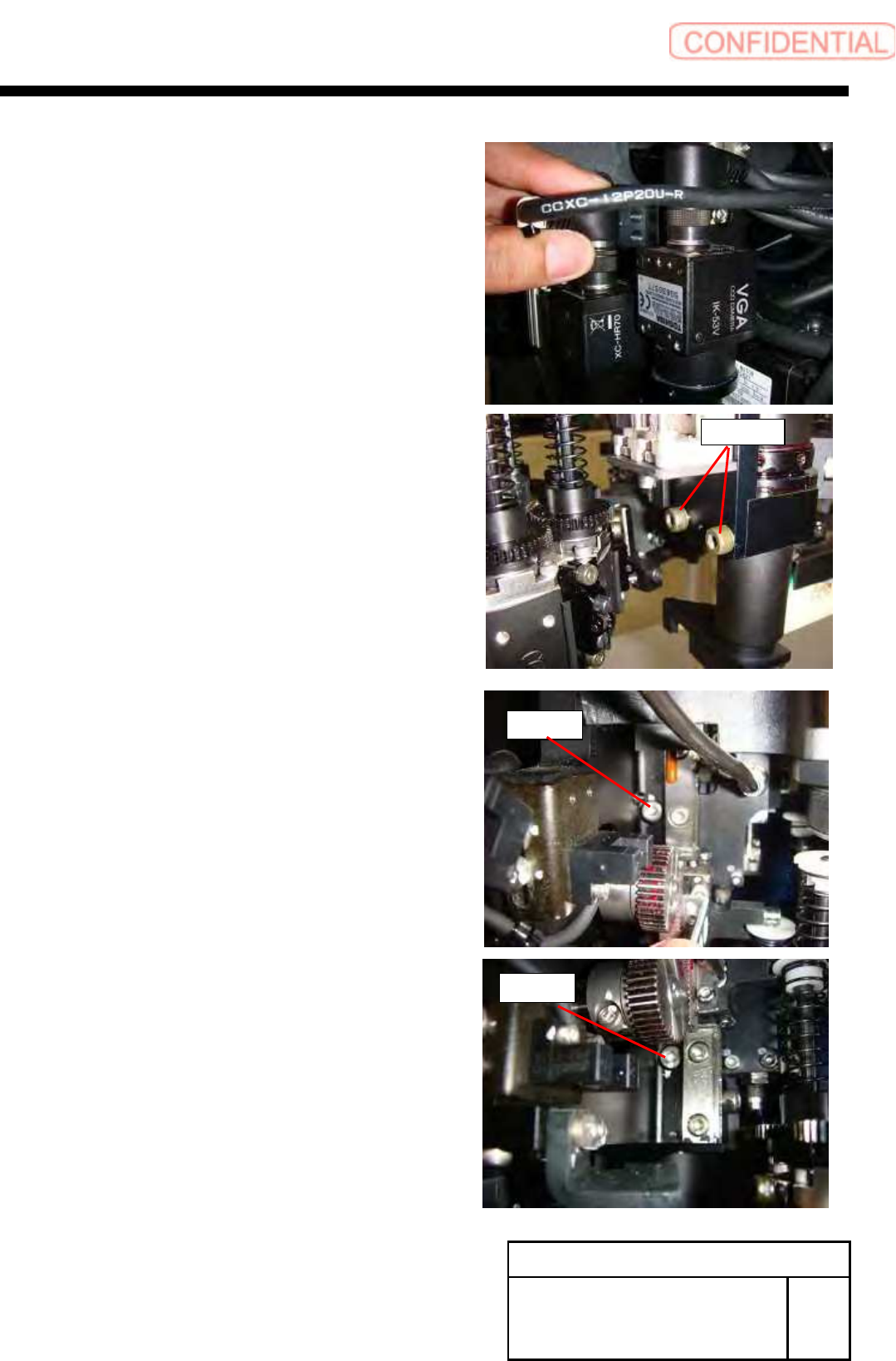
3. Pull out the connector (cam2-U*) of camera cable,
loosen 2-CP4x8, and remove the detection camera.
4. Loosen 2-CP4x6 from the back of the head.
Change Procedure for Head Unit
Lever Assembly
SHEET
2/7
RPGB-11101-1
CP4x8
CP4x6
CP4x6
Change Procedure for Lever Assembly of Head Unit
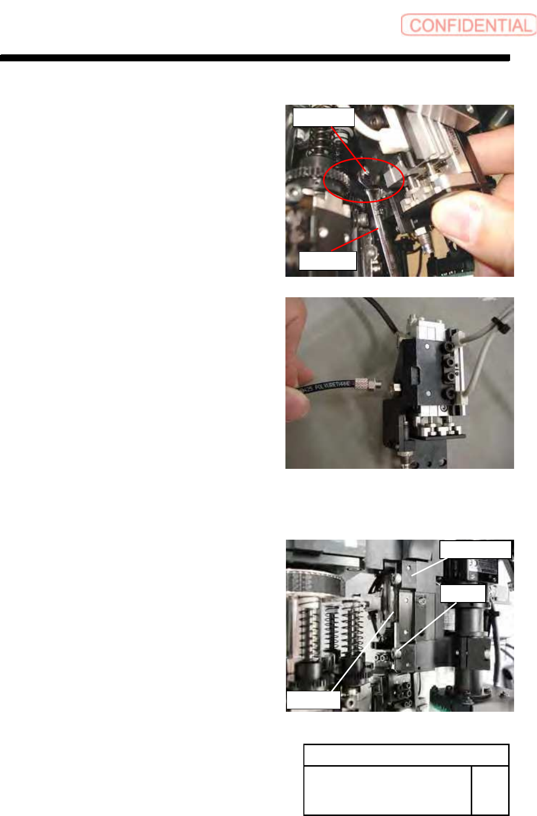
5. Remove the pipe fitting.
Then remove the pickup check up/down unit.
POINT
Use 7mm wrench
4 Remove the 2-C4x16 and the rail holder.
CAUTION
Support the edge of rail when remove the rail holder.
LM guide should not come off for upper side.
After removed it, prevent to come off the tip by cable tie.
Rail Holder
C4x16
LM Guide
Change Procedure for Head Unit
Lever Assembly
SHEET
3/7
RPGB-11101-1
M7 wrench
Pipe Fitting