MAN00000772_SI-G200BB_SVCPDFA.pdf - 第198页
Set-up HLGB-10208-01 Pickup Check Camera Setu p SHEET 2/5 5 Install the stop bracket to the origi nal position with cap screws (4-CP2.5 × 6). Before tightening cap screws (4-CP2.5 × 6), apply small amount of adhesive “14…
Set-up
HLGB-10208-01
Pickup Check Camera Setup
SHEET
1/5
Pickup Check Camera Setup
Perform this working on both heads on the front side and rear side.
[Necessary jigs]
• Length reference nozzle jig
• Scale (about 150 mm)
[Position adjustment for rise end stopper]
1 Move the head to a position where working can be easily performed and turn on the power.
2 Remove the head from the F axis unit.
For removal procedure of F axis unit, refer to the “F axis belt replacing procedure [RPGB-10201-01]”.
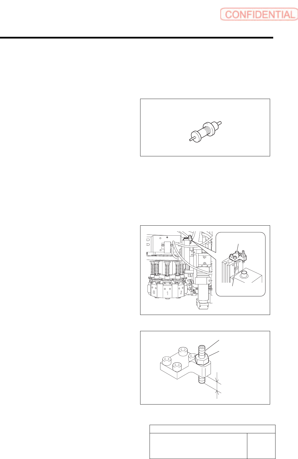
3 Loosen cap screws (4-CP2.5x6) to remove
the stopper bracket.
4 Adjust protrusion amount of the stopper to
4.0mm.
1. Loosen the locknut.
2. Adjust protrusion amount of the
stopper to 4.0mm.
3. Tighten the locknut.
Length reference nozzle jig
Stopper bracket
Cap screw
Stopper
Locknut
4.0 mm
Set-up
HLGB-10208-01
Pickup Check Camera Setup
SHEET
2/5
5 Install the stop bracket to the original
position with cap screws (4-CP2.5×6).
Before tightening cap screws (4-CP2.5×6),
apply small amount of adhesive “1401B” of
THREE BOND to prevent looseness.
6 Install the F axis to the previous state.
[Position adjustment for lowering end stopper]
1 Move the head to a position where working
can be easily performed and turn the power.
2 Install the length reference nozzle jig to the
turret No.1.
3 Lower the pickup check camera.
1. Click in an order of M/C SETUP menu
ORG OFFSET tab ↓Check
button.
2. Press the arrow mark on the right
upper section of the screen.
The Pickup check camera lowers.
Length reference
nozzle jig
Set-up
HLGB-10208-01
Pickup Check Camera Setup
SHEET
3/5
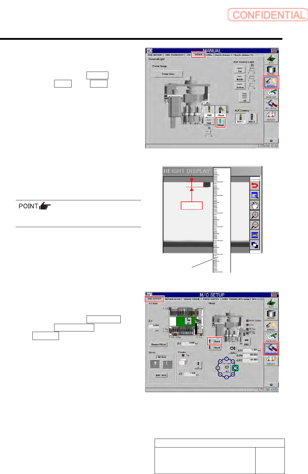
4 Check length of nozzle end displayed on the
HEIGHT DISPLAY screen.
1. Click in an order of Manual
menuVision tab Check button.
Jig nozzle end is displayed on the HEIGHT
DISPLAY screen.
2. Apply a scale on the screen to check
that length of the displayed jig nozzle
end is 3.0mm.
For actual dimension of the nozzle, end of 1mm
is displayed on the screen.
5 Adjust the absorber if the nozzle length on
the HEIGHT DISPLAY screen is not 3.0mm.
1. Click in an order of M/C SETUP
menuORG OFFSET tab
↑ Check button to raise the Pickup
check camera.
Scale
3.0mm