MAN00000772_SI-G200BB_SVCPDFA.pdf - 第144页
O pe r a ti on Guide W o rk Pr ocess Parts R e placem ent Maintenan ce I ntended i tem S I -G200 A A BB Docume n t no. W KGB- 2 0105-0 1 Page 2/8 [Required equipments] Hexagon wrench Nipper Nylon ti e (AB 1 50, AB 100) S…
Operation Guide Work Process Parts Replacement Maintenance
Intended item SI-G200 AA BB
Document no. WKGB-20105-01
Page 1/8
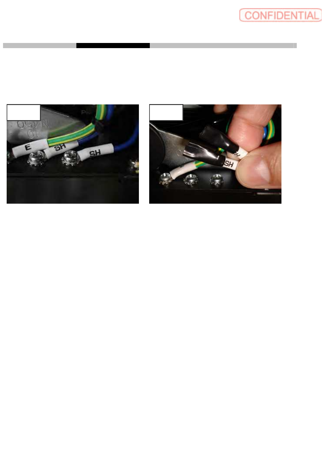
SI-G200 AA BB SH terminals separation to prevent ground relay
Take off SH terminal from machine frame and covers to insulate with plastic tape. After insulation fix
SH lines to prevent interfering during production.
CONTENTS
[Required equipments]...............................................................................................................................2
1. Before work...........................................................................................................................................2
2. Taking off SH terminals of feed cover ................................................................................................ 4
3. Taking off SH terminals of X-Y relay .................................................................................................5
4. Taking off SH terminals of upper frame ............................................................................................7
5. Return back original condition............................................................................................................8
Before After
Operation Guide Work Process Parts Replacement Maintenance
Intended item SI-G200 AA BB
Document no. WKGB-20105-01
Page 2/8
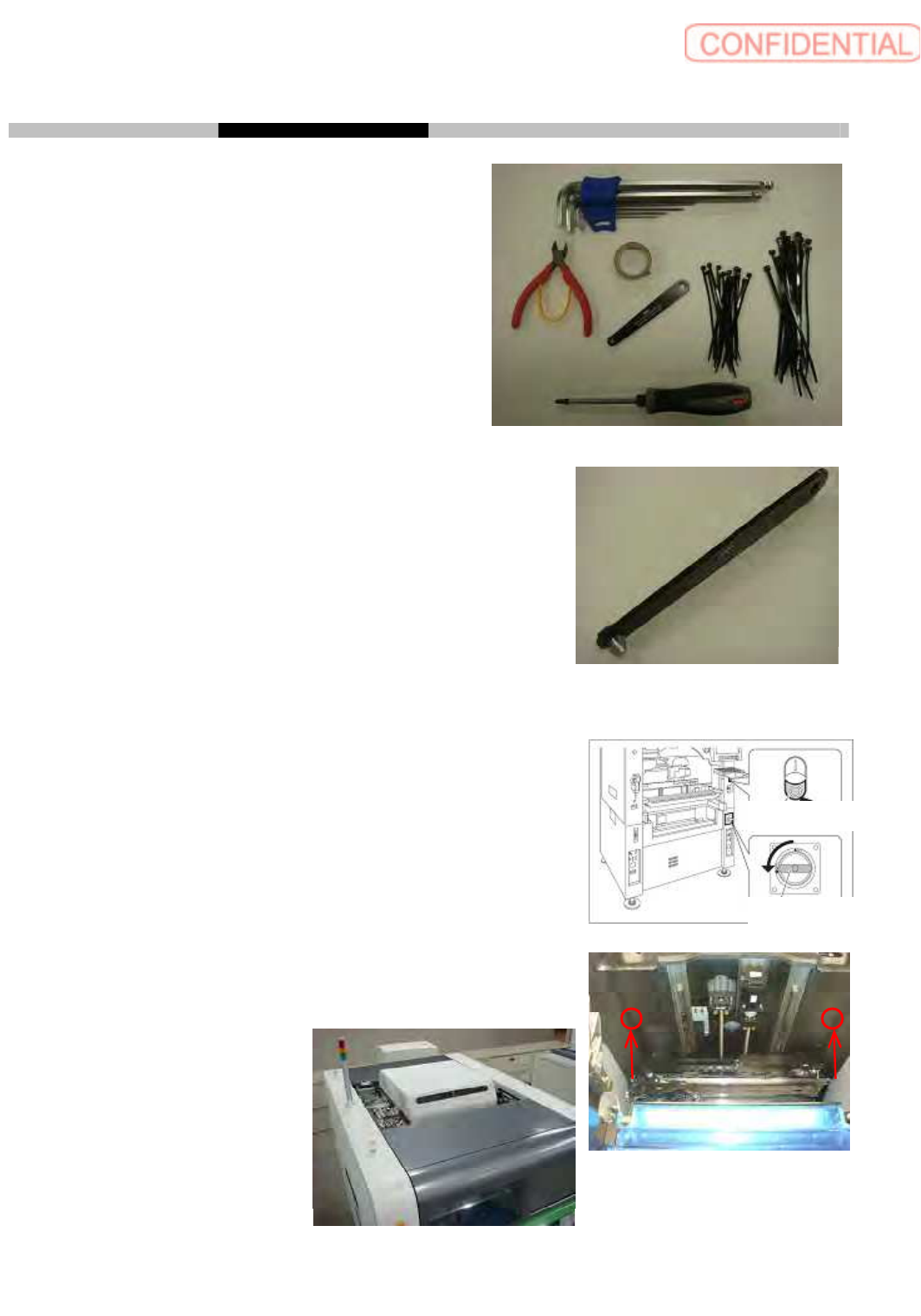
[Required equipments]
Hexagon wrench
Nipper
Nylon tie (AB 150, AB 100)
Screw driver (Plus)
Screw driver plus, with short length (See photo.)
Plastic tape
Screw driver plus, with short length
1. Before work
Power off machine.
Loosen 2 CP 4 x 45 from machine inside shown as photo, to take
off top plate which is on machine both sides.
Power off switch
Main breaker
Operation Guide Work Process Parts Replacement Maintenance
Intended item SI-G200 AA BB
Document no. WKGB-20105-01
Page 3/8
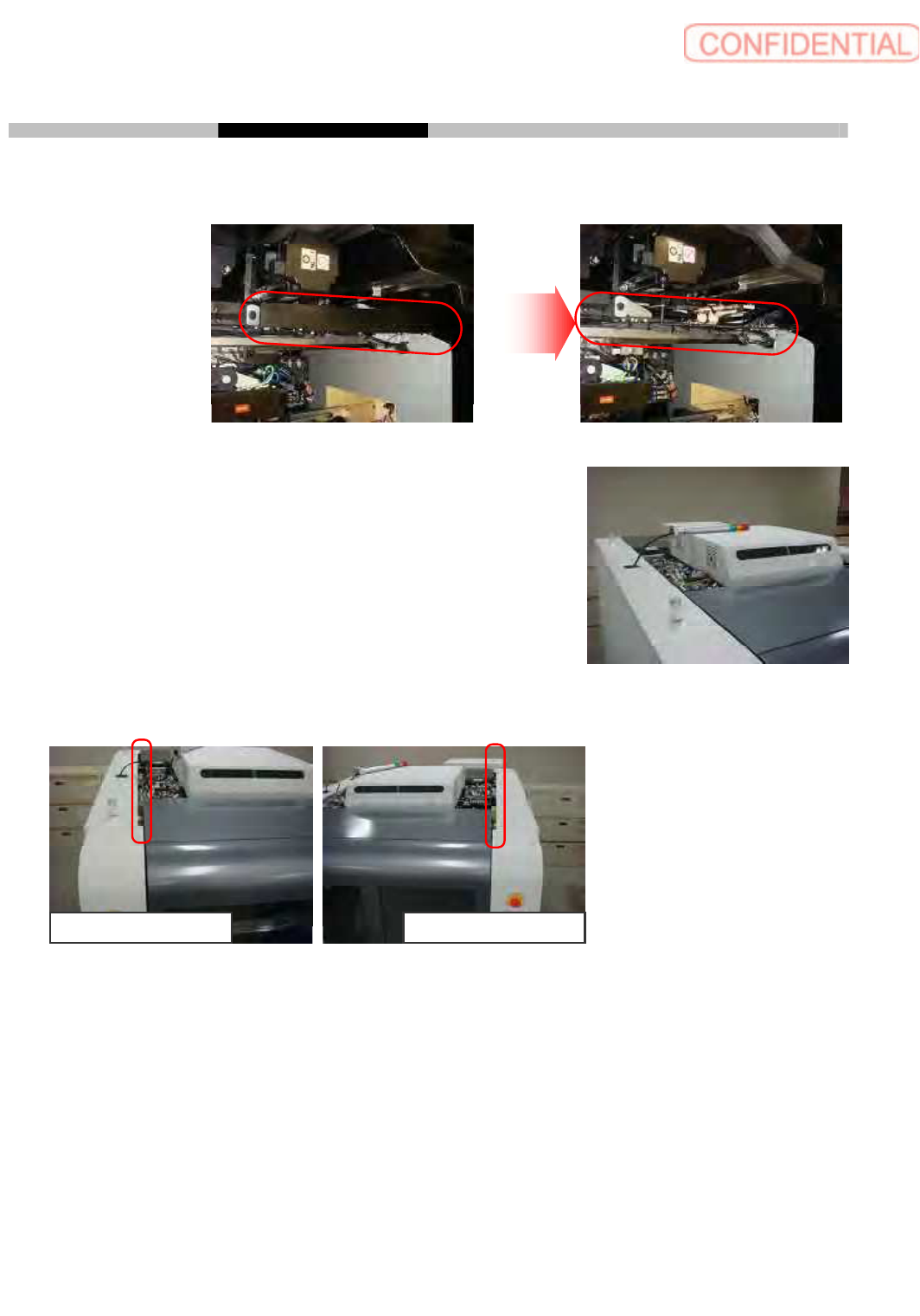
Loosen 8 CP 3 x 6 to take off head connector cover of front side.
Take off head connector cover of rear side as same way.
Loosen 4 CP 4 x 15 to move tower light position from side
sealing to machine top center. It is not requires to take off the
connector which connects tower light and machine.
Loosen 2 CP4 x 8 to shift side sealing position by 10 mm to machine outside.
Now preparation is completed.
Machine Front Left Machine Front Right