MAN00000772_SI-G200BB_SVCPDFA.pdf - 第159页
Preparation for Calibration HLGB-10103-01 Front, Rear LED Control PWB Setup SHEET 1/3 Front, Rear LED Control PWB Setup Setup of LED control board used for SI-G200BB will be explained. Check this setup for the front and …
Preparation for Calibration
HLGB-10102-01
Remove Production Nozzle
SHEET
1/1
Remove Production Nozzle
Remove the nozzle used for production according to the procedure in this section because it is not
used for calibration operation.
[Procedure]
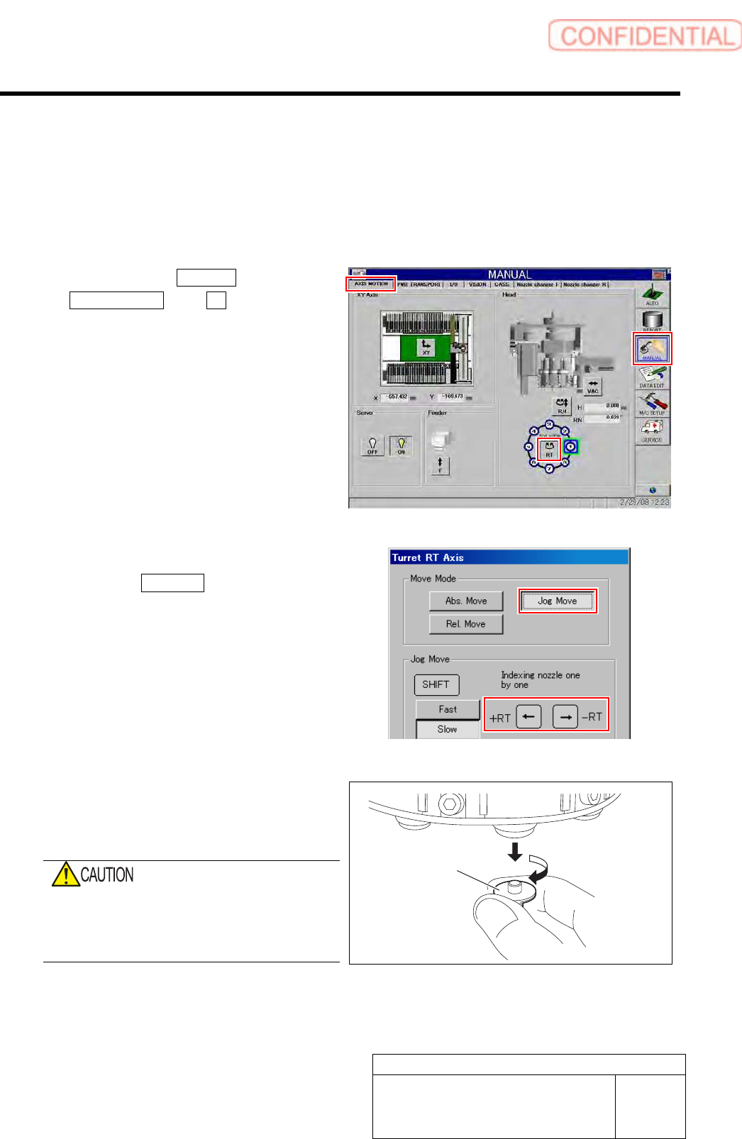
1 Click in an order of MANUAL menu
AXIS MOTION tab RT button.
Turret RT Axis screen is displayed.
2 Move the nozzle to be removed toward you.
1. Click the Jog Move button in the move
mode.
2. Press the cursor key on the left and
right to jog move the nozzle to be
removed toward you.
3 Grab circumference of the nozzle by fingers
and pull out downward with light force while
turning the nozzle slowly.
When removing the nozzle, do not grab the
end of the nozzle.
Otherwise, the nozzle may be deformed,
causing failure of adsorption or placement.
4 Repeat the procedure 2 and 3 to remove all
of the 8 nozzles.
Nozzle
Preparation for Calibration
HLGB-10103-01
Front, Rear LED Control PWB Setup
SHEET
1/3
Front, Rear LED Control PWB Setup
Setup of LED control board used for SI-G200BB will be explained. Check this setup for the front and
rear head respectively.
[Procedure]
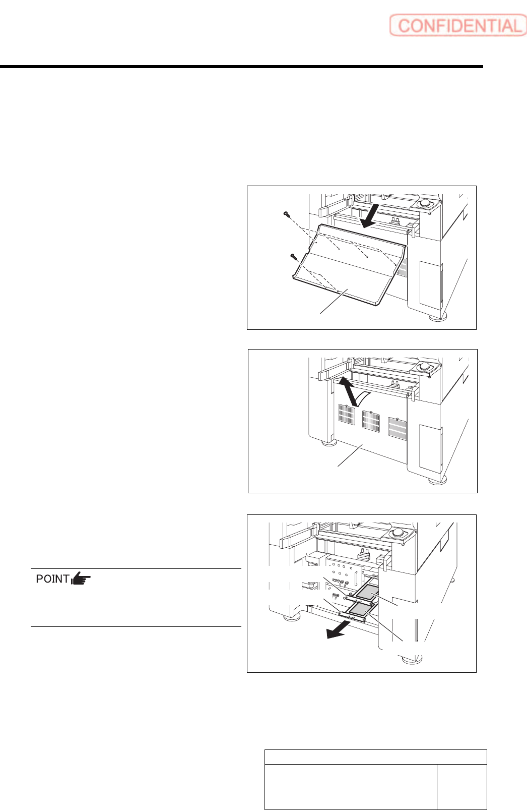
1 Draw out the I/O unit to a position where
working is easily performed.
1. Remove the shooter on the rear of the
unit.
2. Remove the lower cover on the rear of
the unit.
Pull up the lower cover to remove while tilting
the upper of the lower cover toward you.
3. Loosen two screws to draw out the I/O
unit 2 and I/O unit 3.
The front LED control board is stored in the I/O
unit 2, and the rear LED control board is stored
in the I/O unit 3.
Shoote
r
Lower cove
r
Front LED control board
Rear LED control board
I/O unit 2
I/O unit 3
Preparation for Calibration
HLGB-10103-01
Front, Rear LED Control PWB Setup
SHEET
2/3
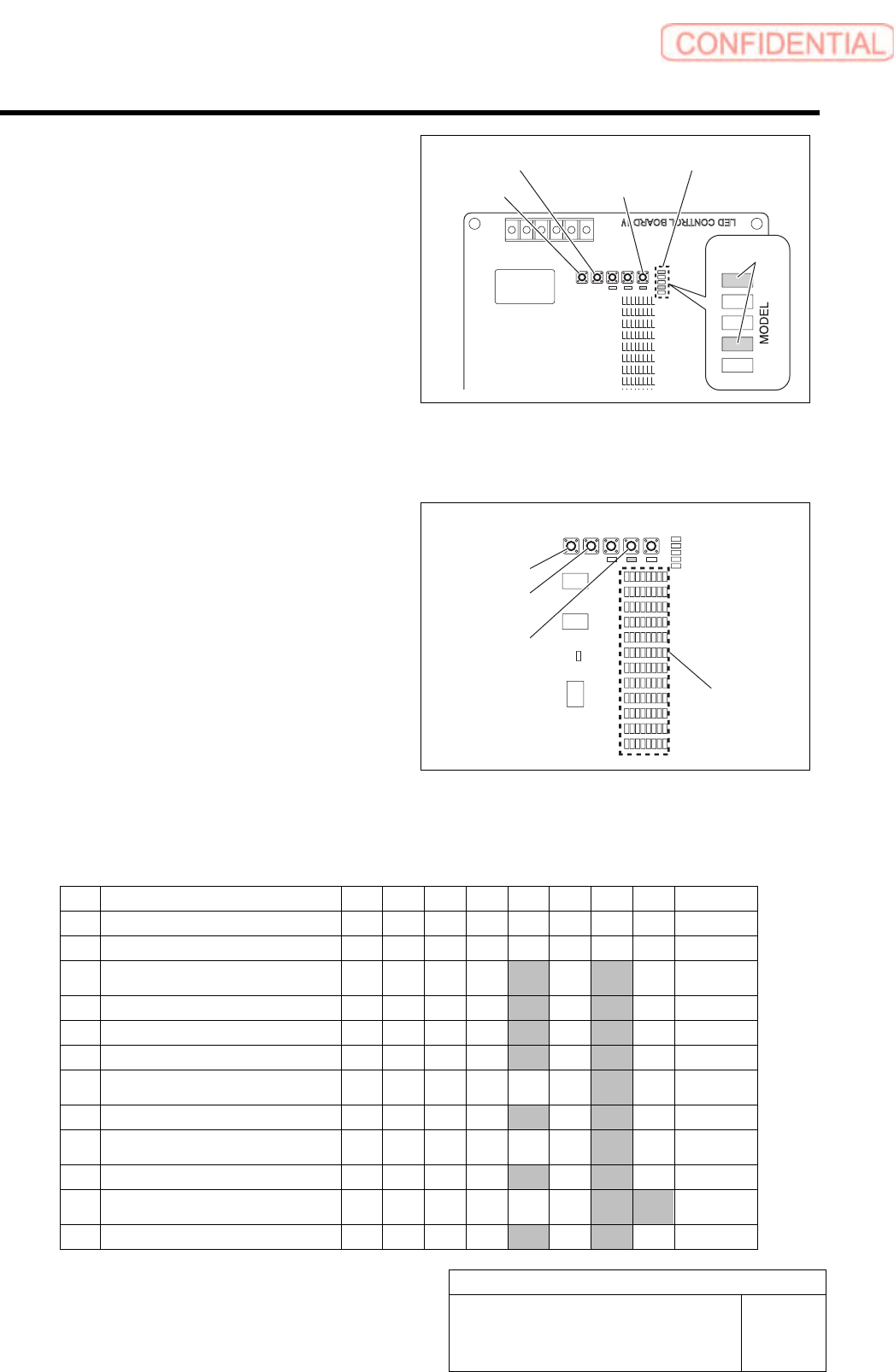
2 Check and change machine type setup of
LED control board.
1. Press the MODEL button for three
seconds or longer.
The MODEL changeover display LED lights up.
2. Check that the LEDs light up at the
position shown in the Fig.
3. If the LED lighting-up state is
different, press the UP/DOWN switch
to change the lighting LED as shown
in the Fig.
4. When ending setup, wait until the
LED lights off.
3 Check and change setup of REF value.
1. Press the REF button for three
seconds or longer.
The LED111 lights up.
2. Press the REF button to select light to
be set up.
3. To change the setting, press the
UP/DOWN button to change so that
the camera setup LED lights up.
4. When ending setup, wait until the
LED lights off.
LED95
|
LED102
LED87
|
LED94
LED7
|
LED14
LED15
|
LED22
LED23
|
LED30
LED31
|
LED38
LED39
|
LED46
LED47
|
LED54
LED55
|
LED62
LED63
|
LED70
LED71
|
LED78
LED79
|
LED86
LED108
|
LED104
SW6
MODEL
SW7
REF
SW3
DATA
SW4
UP
SW5
DOWN
LED103
MODEL
LED110 LED111 LED109
SI-G200BB head REF value setup list
Light 128 64 32 16 8 4 2 1 Value
12 Pickup check (LED7~14) -
11 Not used (LED15~22) -
10
Fixed camera lower stage light2
(LED23~30)
10
9 Not used (LED31~38) 10
8 Parts 45° light (LED39~46) 10
7 Not used (LED47~54) 10
6
Fixed camera lower stage light1
(LED55~62)
2
5 Parts permeable light (LED63~70) 10
4
Fixed camera middle stage light
(LED71~78)
2
3 Parts coaxial light (LED79~86) 10
2
Fixed camera upper stage light
(LED87~94)
3
1 PWB camera light (LED95~102) 10
* Hatched portions mean that the LED lights up.
DOWN button
UP button
MODEL button
MODEL changeover display LED
Lighting up
DOWN button
UP button
REF button
Camera
setup LED