MAN00000772_SI-G200BB_SVCPDFA.pdf - 第190页
Set-up HLGB-10206-01 F Ax is Setup SHEET 3/5 2. Click the Jog Move button. 3. Press the cursor key to m ove the feed part onto the feed adjust ing jig. 4. Place the part feed h eight jig (1 10.4mm) on the feed adjusting …
Set-up
HLGB-10206-01
F Axis Setup
SHEET
2/5
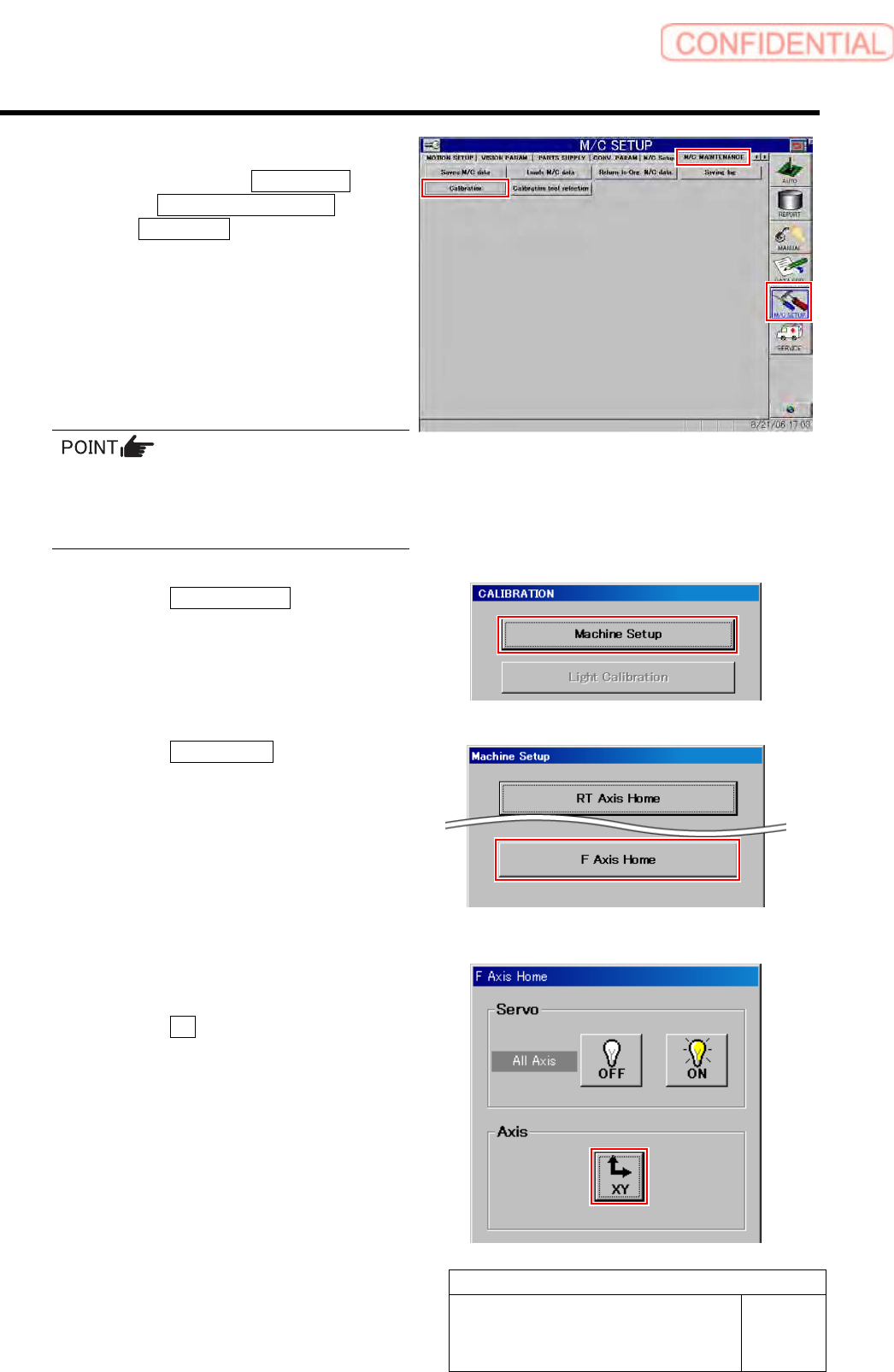
3 Display the F Axis Home screen.
1. Click in an order of M/C SETUP
menuM/C MAINTENANCE
tabCalibration button.
“Head at opposite position will be moved to
noninterference area. Press the [START] button if
you are really OK.” is displayed on the message
screen.
2. Press the [START] button on the
operation panel.
CALIBRATION screen is displayed.
For procedures when selecting head for which
calibration is performed, and when changing
calibration jig, refer to the “How to display
calibration screen (HLGB-10105-01)”.
3. Click the Machine Setup button on the
CALIBRATION screen.
Machine Setup screen is displayed.
4. Click the F Axis Home button.
F Axis Home screen is displayed.
4 Move the feed part onto the feed adjusting
jig.
1. Click the XY button on the F Axis
Home screen.
XY Axis screen is displayed.
Set-up
HLGB-10206-01
F Axis Setup
SHEET
3/5
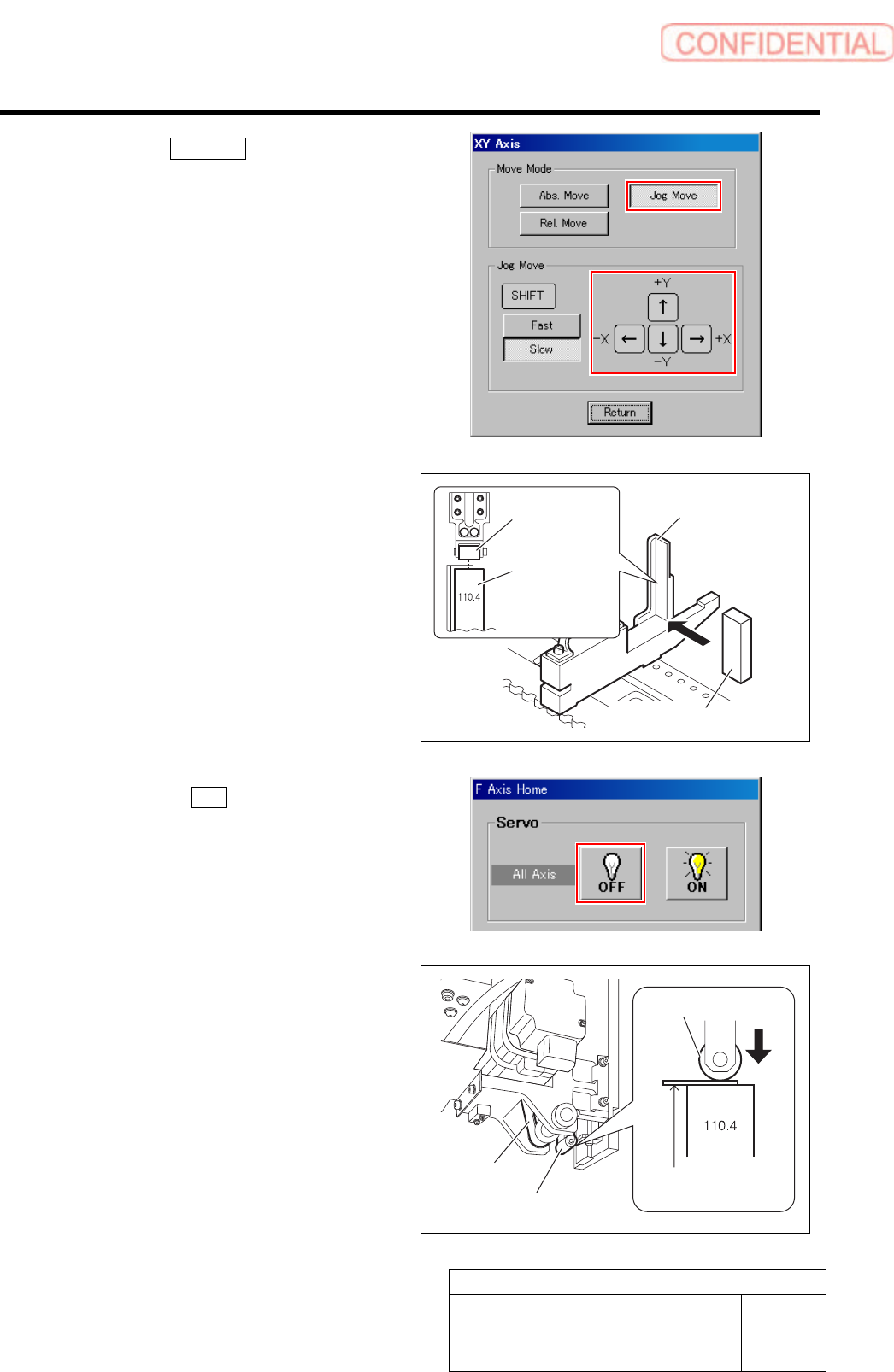
2. Click the Jog Move button.
3. Press the cursor key to move the feed
part onto the feed adjusting jig.
4. Place the part feed height jig
(110.4mm) on the feed adjusting jig.
5. Adjust position so that center of the
feed roller is on the center of the part
feed height jig.
5 Click the servo OFF button on the F Axis
Home screen.
Servos for all axes are turned off.
6 Rotate the pulley of the F axis belt to lower
the feed roller to the setup position.
1. Pinch a thickness gauge of 0.1mm on
the part feed height jig.
2. Rotate the pulley of the F axis belt to
lower the feed roller to a position
where it contacts the thickness gauge.
Feed adjusting jig
Feed roller
Part feed
height jig
Part feed height jig (110.4 mm)
Feed roller
F axis belt
Feed roller
Thickness gauge
(t = 0.1 mm)
Set-up
HLGB-10206-01
F Axis Setup
SHEET
4/5
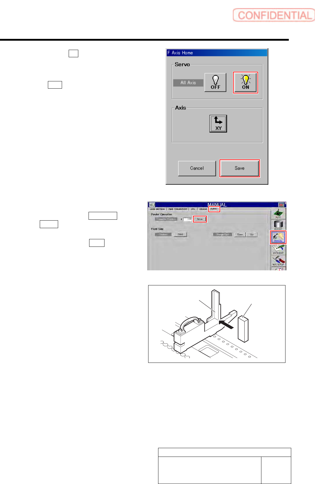
7 Click the servo ON button on the F Axis
Home screen.
Servos for all axes are tuned on.
8 Click the Save button.
Height of the F axis is saved, and the F Axis Home
screen closes.
9 Change the thickness gauge to 0.2mm, and
check that it is not inserted into a gap
between the feed roller and the part feed
height jig.
10 Close the Machine Setup screen and
Calibration Menu screen.
11 Press the [ORG] button on the operation
panel to perform origin position return.
12 Check the set F axis height.
1. Click in an order of MANUAL menu
CASS. tab.
2. Input “120” into the cassette position
space, and click the Move.
3. Press the [START] button on the
operation panel.
The head moves to No.120 cassette position.
4. Replace the parts feed height jig
(110.4mm) on the feed adjustment jig
with a parts feed height jig of 86.5mm.
Feed adjusting jig
Part feed height jig
(86.5 mm)