MAN00000772_SI-G200BB_SVCPDFA.pdf - 第216页
Calibration HLGB-10304-01 Auto Calibration (Recognition of relationship betw een PWB coordinate and mechanism coordinat e) SHEET 6/7 2. Press the [Start] button to start the auto calibration. Captive check screen for jig…
Calibration
HLGB-10304-01
Auto Calibration (Recognition of
relationship between PWB coordinate and
mechanism coordinate)
SHEET
5/7
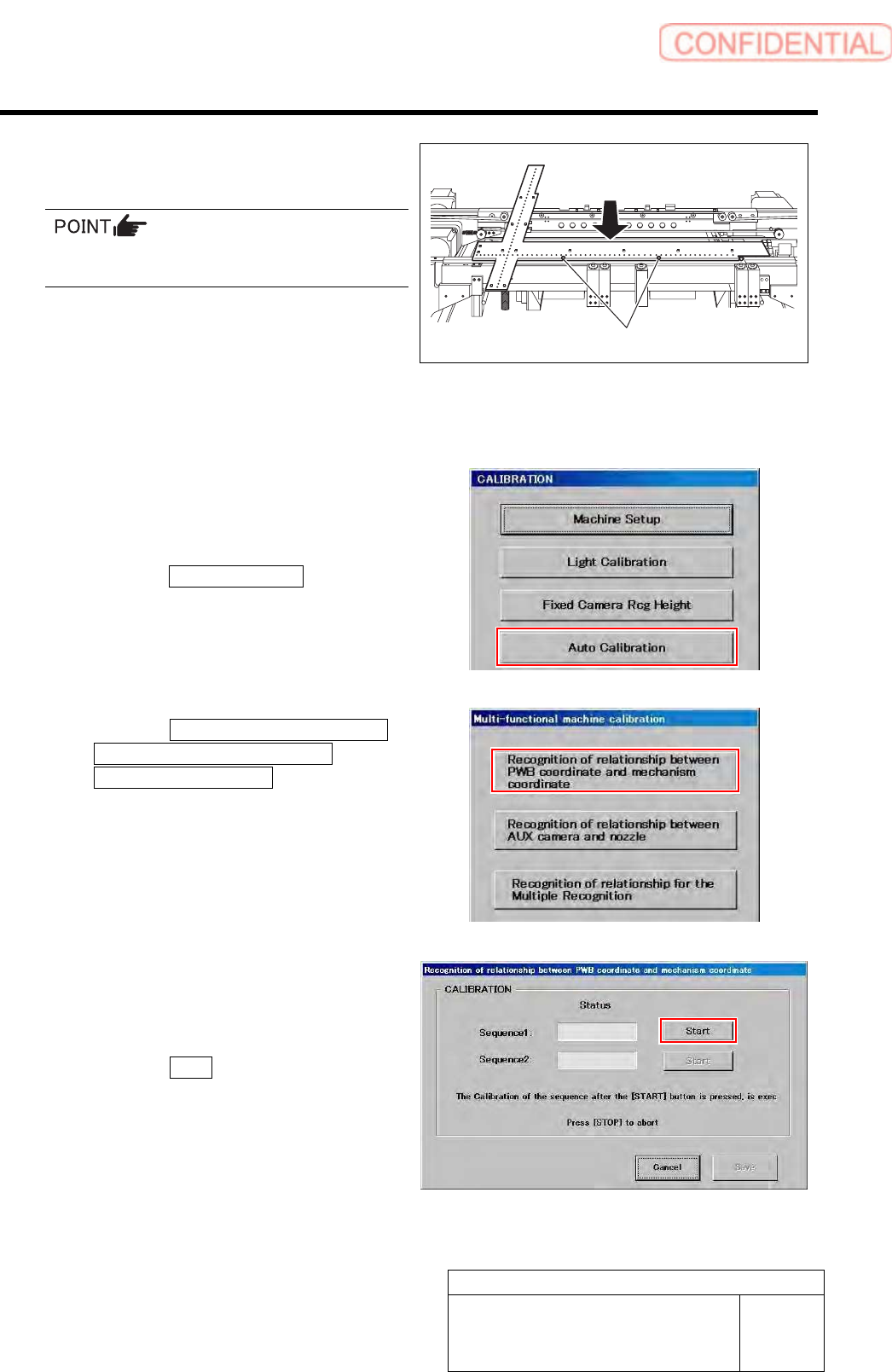
3. Attach the positioning pins to lock the
jig.
Before attaching the positioning pins, make sure
the base point jig is seated securely.
4. After attaching the positioning pins,
pull the jig slightly toward you so that
the jig comes parallel with the transfer
rail of the fixed side.
9 Display a Recognition of relationship
between PWB coordinate and mechanism
coordinate screen.
1. Click the Auto Calibration button on
the CALIBRATION screen.
Multi-functional machine calibration screen is
displayed.
2. Click the Recognition of relationship
between PWB coordinate and
mechanism coordinate button on the
Multi-functional machine calibration
screen.
Recognition of relationship between PWB
coordinate and mechanism coordinate screen is
displayed.
10 Start calibration for relationship between the
PWB coordinate and mechanical
coordinate.
1. Click the Start button of Sequence 1.
Positioning pin
Calibration
HLGB-10304-01
Auto Calibration (Recognition of
relationship between PWB coordinate and
mechanism coordinate)
SHEET
6/7
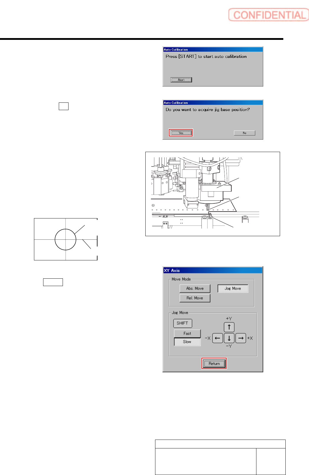
2. Press the [Start] button to start the
auto calibration.
Captive check screen for jig base position is
displayed.
3. Click the Yes button.
XY Axis screen is displayed.
4. Align the PWB camera to the
reference position on the front of the
locator pin while checking the
PCBOARD DISPLAY.
Align cross-hair line on the PCBOARD
DISPLAY to the center of the hole of the
reference position by jog move.
5. The calibration starts when you click
the Return button on the XY Axis
window.
Wait until the calibration process ends.
PWB camera
Reference
position
Locator pin
Hole of reference
position
Cross-hair line
Calibration
HLGB-10304-01
Auto Calibration (Recognition of
relationship between PWB coordinate and
mechanism coordinate)
SHEET
7/7
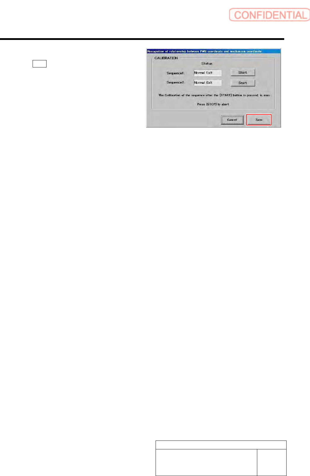
11 Check that it was normally ended, and click
the Save button.
Calibration result is saved.
12 Remove the ball point jig, and then reattach
the rail stopper, PWB presser rails, and
nozzle cartridges to their original location.
13 Go on to the procedure of recognition of relationship between the fixed camera and nozzle, and
then to the procedure of Recognition of relationship for the Multiple Recognition.
・ For the recognition of relationship between the fixed camera and nozzle procedure, refer to “Auto Calibration
(Recognition of Relationship between the Fixed Camera and Nozzle)[HLGB-10305-01]”.
・ For the recognition of relationship for the Multiple Recognition procedure, refer to “Auto Calibration (Recognition of
relationship for the Multiple Recognition)[HLGB-10306-01]”.