MAN00000772_SI-G200BB_SVCPDFA.pdf - 第281页
Calibration HLGB-10315-01 Conv ey or Wi d th A djus tme nt SHEET 2/2 4 Set offset value of convey or on the conveyor parameter screen. 1. Click in an order of M/ C SETUP men u CONV . P ARAM tab. Conveyor parameter scre…
Calibration
HLGB-10315-01
Conveyor Width Adjustment
SHEET
1/2
Conveyor Width Adjustment
[Procedure]
1 Perform origin position return of conveyor.
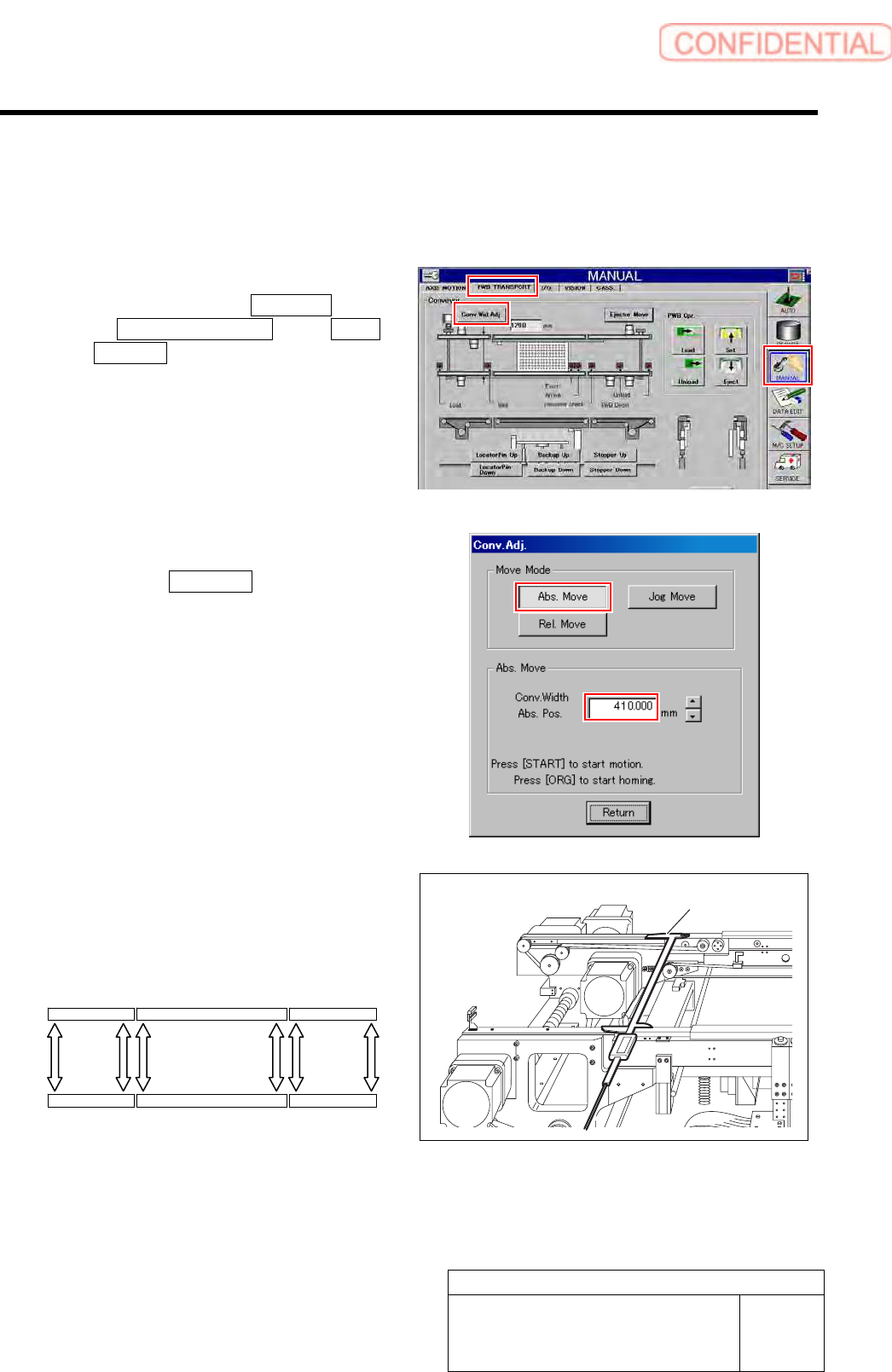
1. Click in an order of MANUAL menu
PWB TRANSPORT tab Conv.
Wid. Adj. button.
Conv. Adj. screen is displayed.
2. Press the [ORG] button on the
operation panel with the Conv. Adj.
screen being displayed.
Conveyor return to origin.
2 Set the conveyor width to 410 mm.
1. Click the Abs. Move button on the
Conv. Adj. screen.
2. Input “410” into the input box of the
Conv. Width Abs. Pos.
3. Press the [START] button on the
operation panel.
Conveyor width is widened to the position of 410
mm.
3 Measure conveyor width on the following six
locations with digital caliper.
Take notes of measured values.
Digital caliper
Conveyor L Middle conveyor Conveyor R
(1) (2) (3) (4) (5) (6)
Calibration
HLGB-10315-01
Conveyor Width Adjustment
SHEET
2/2
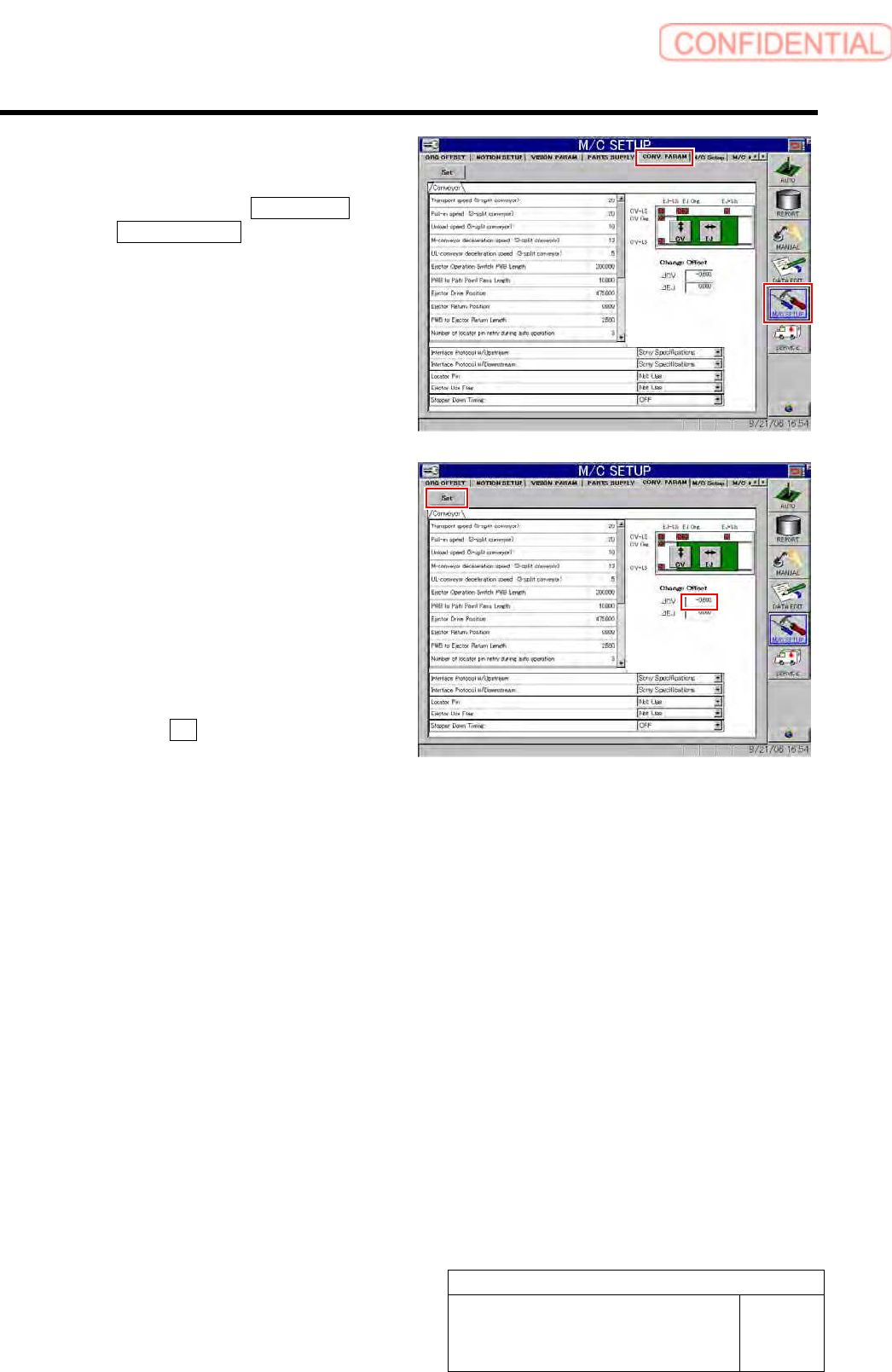
4 Set offset value of conveyor on the conveyor
parameter screen.
1. Click in an order of M/C SETUP menu
CONV. PARAM tab.
Conveyor parameter screen is displayed.
2. Enter a difference value between the
value of narrowest conveyor width
measured in the procedure 3 and the
standard value “410.5 mm” into the
CV offset box.
Example: Measured value: 410.1 mm
•••••••••Input value “-0.4”
Measured value: 410.7 mm
•••••••••Input value “0.2”
3. Click the Set button.
Offset value for conveyor width is set.
5 Manually move the conveyor width to 410 mm again, and check that the conveyor width is within
the standard value (410.5 mm) with digital slide calipers in the same procedure as in the
procedures 1 to 3.
If the conveyor width is not within the standard value, repeat the procedures 1 to 4 until the conveyor width falls within
the standard value.
Calibration
HLGB-10316-01
Measuring Parallelism of Reference
Pin and Dependent Pin
SHEET
1/4
Measuring Parallelism of Reference Pin and Dependent Pin
[Procedure]
1 Perform origin position return of the unit.
1. Press the [ORG] button on the operation panel with the HI screen being displayed.
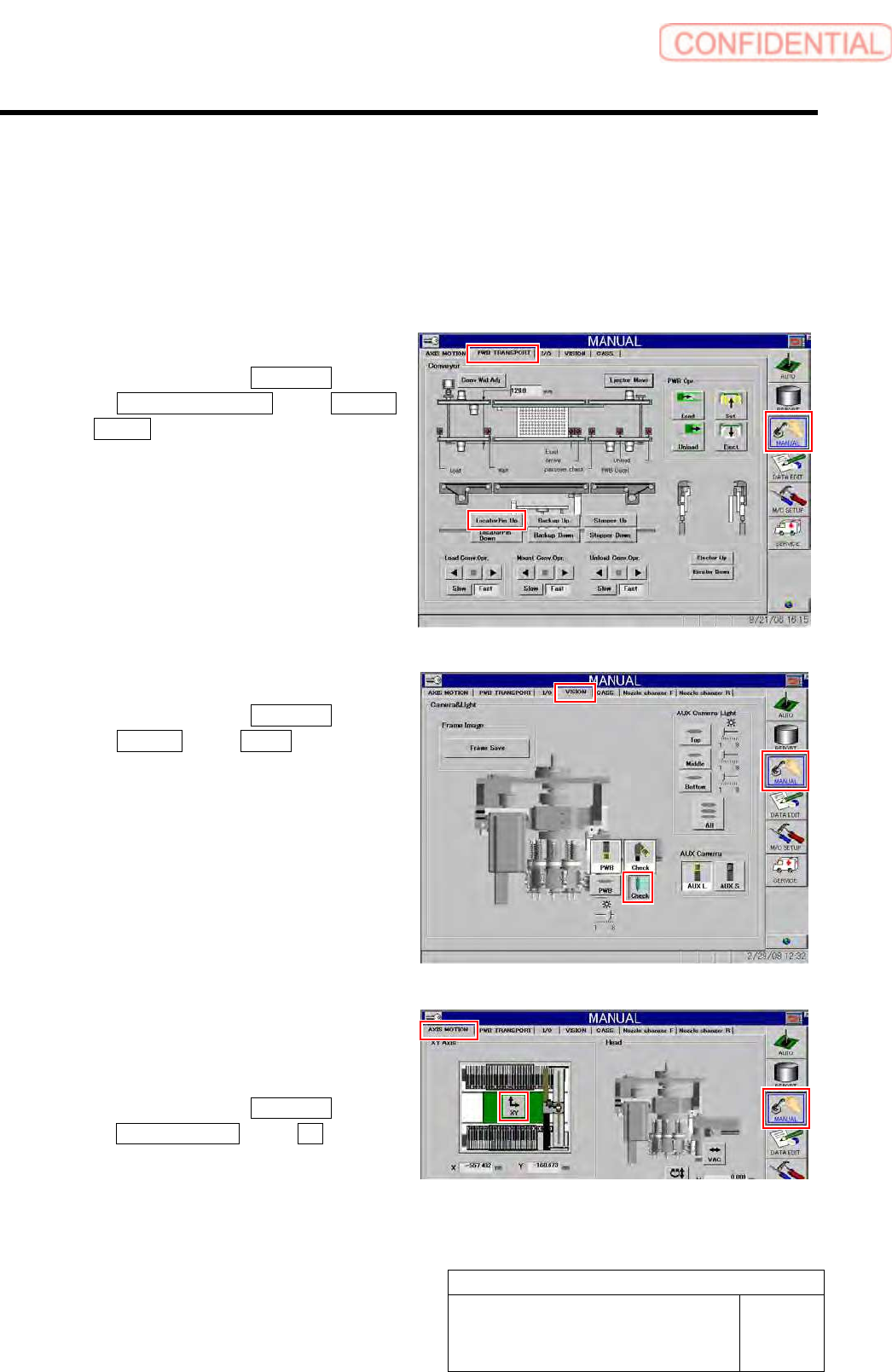
2 Raise the reference pin.
1. Click in an order of MANUAL menu
PWB TRANSPORT tab Locator
Pin Up button.
3 Light up the PWB camera light.
1. Click in an order of MANUAL menu
VISION tab Check button.
The pickup camera light lights up.
4 Check Y axis coordinate at a position where
the reference pin is displayed at the center
of the “PCBOARD DISPLAY” screen.
1. Click in an order of MANUAL menu
AXIS MOTION tab XY button.
XY Axis screen is displayed.