MAN00000772_SI-G200BB_SVCPDFA.pdf - 第591页
Alarm List for the Servo Pack "S igma-III" Series (SGDS type) BBGB-10101-01 Alarm List for the Servo Pack "Sigma-III" Series (SGDS type) SHEET 2/18 Alarm Display Alarm Name Situation at Alarm Occurren…
Alarm List for the Servo Pack "Sigma-III" Series (SGDS type)
BBGB-10101-01
Alarm List for the Servo Pack
"Sigma-III" Series (SGDS type)
SHEET
1/18
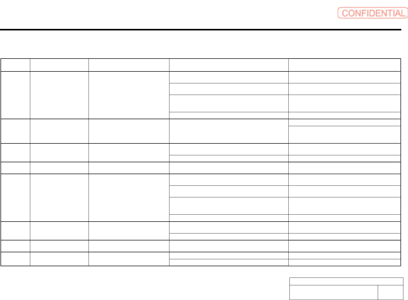
Alarm List for the Servo Pack "Sigma-III" Series (SGDS type)
Alarm
Display
Alarm Name Situation at Alarm Occurrence Cause Corrective Actions
The control power supply lowered and sometimes ranged from
30 VAC to 60 VAC.
Correct the power supply, and set Fn005 to initialize the
parameter.
The power supply was turned OFF while changing the
parameter setting.
Set Fn005 to initialize the parameter and input the
parameter again.
The number of times that parameters were written exceeded
the upper limit. For example, the parameter was changed every
scan through the host controller.
Replace the SERVOPACK.
A.020 Parameter Checksum Error 1 Occurred when the control power supply
was turned ON.
The SERVOPACK EEPROM and the related circuit are faulty. Replace the SERVOPACK.
Replace the SERVOPACK. A.021 Parameter Format Error Occurred when the power was turned ON
again after writing the parameter with the
parameter copy function of the digital
operator (JUSP-OP05A).
The model number of the SERVOPACK in the software being
used for the SERVOPACK is old and not compatible with the
current parameters.
Change the parameter settings to be compatible with the
model number in the software being used for the
SERVOPACK.
The control power supply lowered and sometimes ranged from
30 VAC to 60 VAC.
Correct the power supply, and set Fn005 to initialize the
parameter.
A.022 System Parameter Checksum
Error 1
Occurred when the control power supply
was turned ON.
The SERVOPACK EEPROM and the related circuit are faulty. Replace the SERVOPACK.
A.023 Parameter Password Error Occurred when the control power supply
was turned ON.
A SERVOPACK board fault occurred. Replace the SERVOPACK.
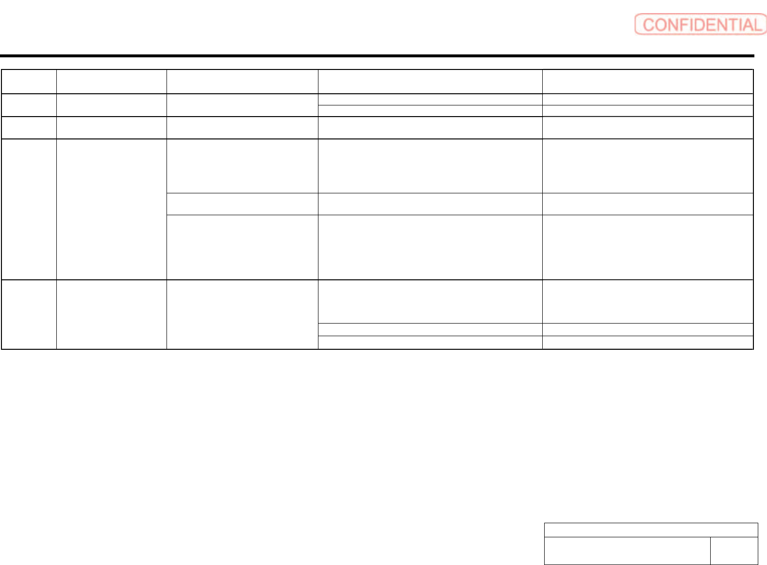
The control power supply lowered and sometimes ranged from
30 VAC to 60 VAC.
Correct the power supply, and set Fn005 to initialize the
parameter.
The power supply was turned OFF while changing the
parameter setting.
Set Fn005 to initialize the parameter and input the
parameter again.
The number of times that parameters were written exceeded
the upper limit. For example, the parameter was changed every
scan through the host controller.
Replace the SERVOPACK.
A.02A Parameter Checksum Error 2 Occurred when the control power supply
was turned ON.
The SERVOPACK EEPROM and the related circuit are faulty. Replace the SERVOPACK.
The control power supply lowered and sometimes ranged from
30 VAC to 60 VAC.
Correct the power supply, and set Fn005 to initialize the
parameter.
A.02b System Parameter Checksum
Error 2
Occurred when the control power supply
was turned ON.
The SERVOPACK EEPROM and the related circuit are faulty. Replace the SERVOPACK.
A.030 Main Circuit Detector Error Occurred when the control power supply
was turned ON or during operation.
A SERVOPACK fault occurred. Replace the SERVOPACK.
Parameter is set out of range. Set the parameter within the specified range. A.040 Parameter Setting Error 1 Occurred when the control power supply
was turned ON.
The SERVOPACK EEPROM and the related circuit are faulty. Replace the SERVOPACK.
Alarm List for the Servo Pack "Sigma-III" Series (SGDS type)
BBGB-10101-01
Alarm List for the Servo Pack
"Sigma-III" Series (SGDS type)
SHEET
2/18
Alarm
Display
Alarm Name Situation at Alarm Occurrence Cause Corrective Actions
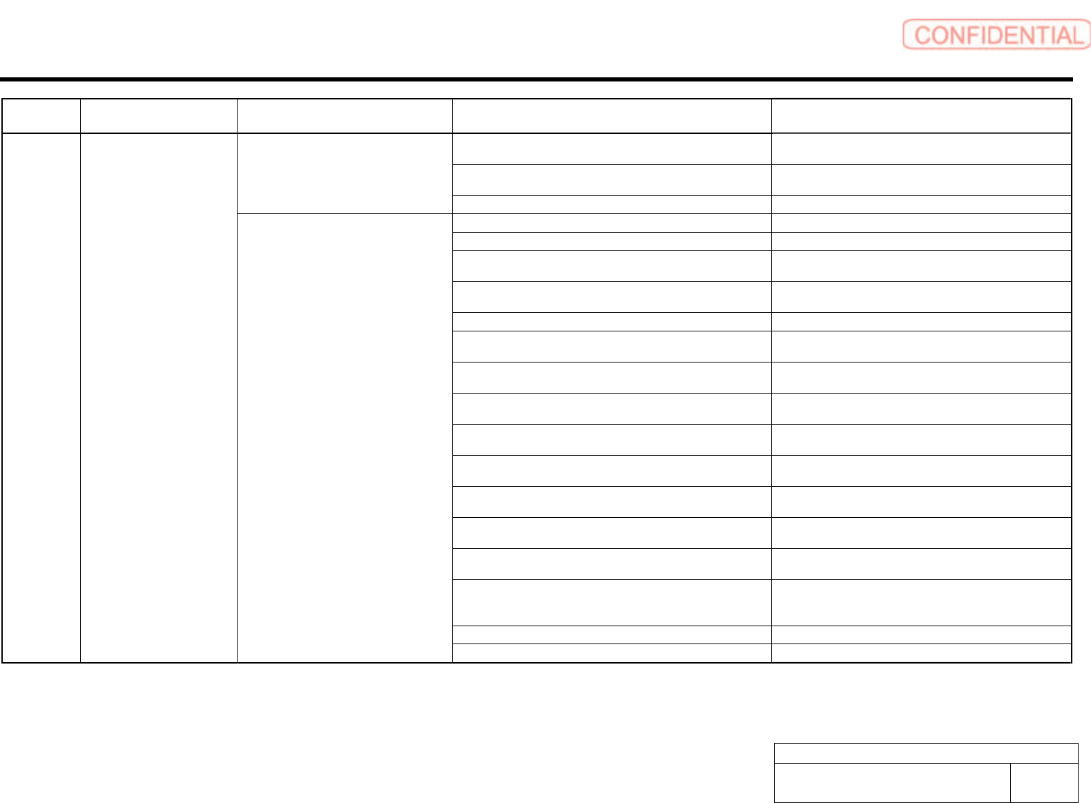
Parameter is set out of range. Set the parameter within the specified range. A.04A Parameter Setting Error 2 Occurred when the control power supply
was turned ON.
The SERVOPACK EEPROM and the related circuit are faulty. Replace the SERVOPACK.
A.041 Dividing Pulse Output Setting
Error
Occurred when the control power supply
was turned ON.
The PC dividing pulse set for Pn212 is out of the setting range
and does not satisfy the setting conditions.
Set Pn212 to the correct value.
Occurred when the power was turned ON
again after changing electronic gear ratio
(Pn20E/Pn210) or changing the motor to
the one with different number of encoder
pulses.
Speed of program JOB operation (Fn004) is out of range by
changing electronic gear ratio (Pn20E/Pn210) or motor.
Reduce electronic gear ratio (Pn20E/Pn210).
Occurred when program JOG movement
speed (Pn533) is changed.
Speed of program JOB operation (Fn004) is out of range by
changing program JOG movement speed (Pn533).
Increase program JOG movement speed (Pn533).
A.042 Multiple Parameter
Combinations Exceeding Set
Range
Occurred when attempting to execute
advanced auto tuning (F017) after
changing electronic gear ratio
(Pn20E/Pn210) or changing the motor to
the one with different number of encoder
pulses.
Movement speed of advanced auto tuning is out of range by
changing electronic gear ratio (Pn20E/Pn210) or motor.
Reduce electronic gear ratio (Pn20E/Pn210).
The SERVOPACK and servomotor capacities do not
correspond to each other.
Servomotor capacity / SERVOPACK capacity ≤ 1/4
or servomotor capacity / SERVOPACK capacity ≥ 4
Select the proper combination of SERVOPACK and
servomotor capacities.
The parameter that is written in the encoder is incorrect. Replace the servomotor (encoder).
A.050 Combination Error Occurred when the control power supply
was turned ON.
A SERVOPACK board fault occurred. Replace the SERVOPACK.
Alarm List for the Servo Pack "Sigma-III" Series (SGDS type)
BBGB-10101-01
Alarm List for the Servo Pack
"Sigma-III" Series (SGDS type)
SHEET
3/18
Alarm
Display
Alarm Name Situation at Alarm Occurrence Cause Corrective Actions
The overload alarm has been reset by turning OFF the power
too many times.
Change the method to reset the alarm.
The connection is faulty between the SERVOPACK board and
the thermostat switch.
Replace the SERVOPACK.
Occurred when the control power supply
was turned ON.
The SERVOPACK board fault occurred. Replace the SERVOPACK.
The connection between grounding and U, V, or W is incorrect. Check and then correct the wiring.
The grounding line has contact with other terminals. Check and then correct the wiring.
A short circuit occurred between the grounding and U, V, or W
of the servomotor cable.
Repair or replace the servomotor cable.
A short circuit occurred between phase U, V, or W of the
servomotor.
Repair or replace the servomotor cable.
The wiring of the regenerative resistor is incorrect. Check and then correct the wiring.
A short circuit occurred between the grounding and U, V, or W
of the SERVOPACK.
Replace the SERVOPACK.
A SERVOPACK fault occurred (current feedback circuit, power
transistor or board fault).
Replace the SERVOPACK.
A short circuit occurred between the grounding and U, V, W of
the servomotor.
Replace the servomotor.
A short circuit occurred between the grounding and U, V, W of
the servomotor.
Replace the servomotor.
A fault occurred in the dynamic brake circuit. Replace the SERVOPACK, and reduce the load, or reduce
the number of rotations used.
The dynamic brake was activated too frequently, so a DB
overload alarm occurred.
Replace the SERVOPACK, and reduce the DB operation
frequency.
The overload alarm has been reset by turning OFF the power
too many times.
Change the method to reset the alarm.
The overload or regenerative power exceeds the regenerative
resistor's capacity.
Reconsider the load and operation conditions.
The direction or the distance of the SERVOPACK to other
devices is incorrect.
Heat radiation of the panel or heat around the panel occurred.
The ambient temperature for the SERVOPACK must be
55-degrees centigrade or less.
A SERVOPACK fan fault occurred. Replace the SERVOPACK.
A.100 Overcurrent
(Heat Sink Overheated)
Occurred when the main circuit power
supply was turned ON or when an
overcurrent occurred while the servomotor
was running.
A SERVOPACK fault occurred. Replace the SERVOPACK.