MAN00000772_SI-G200BB_SVCPDFA.pdf - 第293页
Adjustment HLGB-10403-01 H A xis Gear Z-phase Matching SHEET 1/5 H Axis Gear Z-phase Matching Perform this working on both heads on the front sid e and rear side. [Necessary jigs] • Thickness ga uge (t=1.0 mm) [Procedure…
Adjustment
HLGB-10402-01
Matching of Y Axis Z-Phase
SHEET
3/3
8 Adjust the Z-phase setup position.
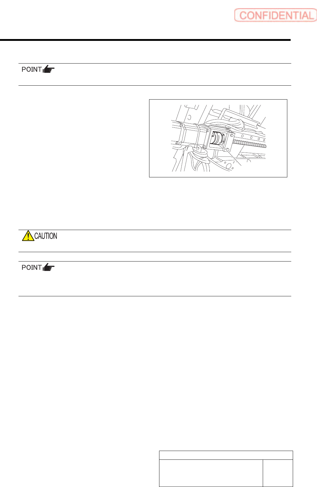
Adjust the Z-phase setup position by adjusting the positional relation between the motor and ball screw.
1. Move the rear head to the center of Y
axis to secure working space to loosen
the coupling screws.
2. Loosen the M5 screw located on the
ball screw side of the coupling for the
front Y axis.
3. One of workers should hold the coupling for the front Y axis located on the unit rear side so
as to prevent the coupling from moving.
4. The other worker should adjust the Y axis so that a distance between the LM guide rail end
on the unit front side and the LM guide face becomes the target dimension (61mm) derived
by the procedure 7.
When the Y axis is moved, the coupling should not be moved.
If the difference between the present amount of movements and the amount of Z-phase setup movement is
positive, move the Y axis to the CCW sensor side (front direction), and if the difference is negative, move it
to the CW sensor (rear direction).
5. Fasten the screw M5 on the ball screw side of the coupling with a torque driver.
Tightening torque :7.0 N・m
9 Turn the emergency stop switch in the arrow direction to release the emergency stop state.
10 Press the [ORG] button on the operation panel to perform origin position return.
11 Check the Z-phase setup position.
1. Measure the distance from the LM guide rail end to the LM guide face with a scale.
Suppose that this measured value is A.
2. Measure the dog detection position of the ORG sensor with a scale. Suppose that the
measured value is B.
Check that a relation is obtained as A (Z-phase set-up position) = B - 5 mm (Z-phase set-up movement amount)
Tolerance level : ±2 mm (Target value:±1 mm)
Coupling
Adjustment
HLGB-10403-01
H Axis Gear Z-phase Matching
SHEET
1/5
H Axis Gear Z-phase Matching
Perform this working on both heads on the front side and rear side.
[Necessary jigs]
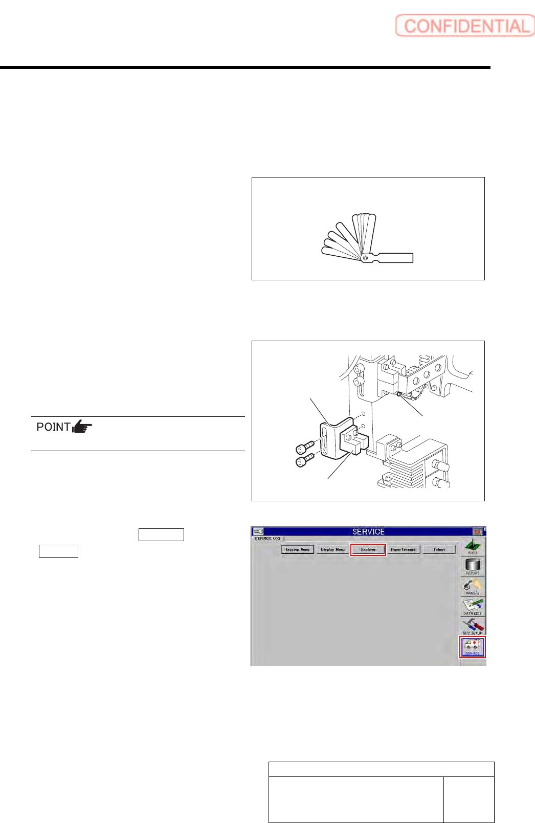
• Thickness gauge (t=1.0 mm)
[Procedure]
1 Remove the lower end sensor (H-CW)
together with the bracket.
2 Loosen split fastening screw on the H axis
motor pinion to make free from motor shaft.
Rotate pinion for easy access of alain key.
3 Click in an order of SERVICE menu
Explorer button.
Explorer screen is displayed.
Thickness gauge (t=1.0mm)
Bracket
Lower end sensor (H-CW)
Split fastening screw
Adjustment
HLGB-10403-01
H Axis Gear Z-phase Matching
SHEET
2/5
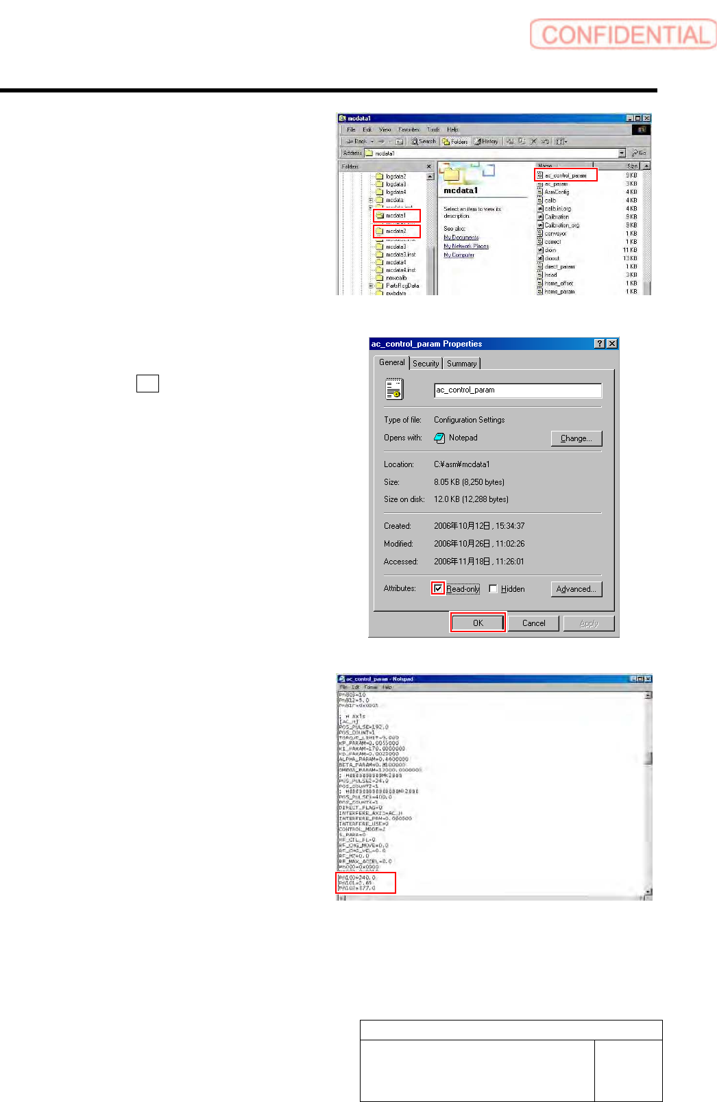
4 Put ac_control_param.ini file for front side
and rear side into a rewritable status.
1. For the front side, open Properties
window for ac_control_param.ini file
in C:¥asm¥mcdata1.
2. For the rear side, open Properties
window for ac_control_param.ini file
in C:¥asm¥mcdata2.
Right-click the file and select “Properties” from
the shortcut menu to open the Properties window.
3. Uncheck “Read-only” on the Properties
window of the ac_param.ini file.
4. Click the OK button.
5 Change the values in the
ac_control_param.ini file for the front side
and rear side.
1. Open the ac_control_param.ini file by
Notepad.
2. Change the value of
PN100-PN101-PN102 of [AC_H].
PN100 (Speed Loop Gain) 180.0 40.0
PN101
(Speed Loop Integral Constant) 3.54 20.0
PN102 (Position Loop Gain) 282.7 40.0
3. Save the ac_control_param.ini file and
end.
4. Open the Properties window of the
ac_control_param.ini file and check
the “Read-only”.