MAN00000772_SI-G200BB_SVCPDFA.pdf - 第328页
Adjustment HLGB-10414-01 Phase A djustment for Nozzle SHEET 3/7 4 Remove the inner shaf t for turret No.1. 1. Click the RT button on the Axis MOTION screen. T urret R T Axis s creen is displayed. 2. Click the Jog Move bu…
Adjustment
HLGB-10414-01
Phase Adjustment for Nozzle
SHEET
2/7
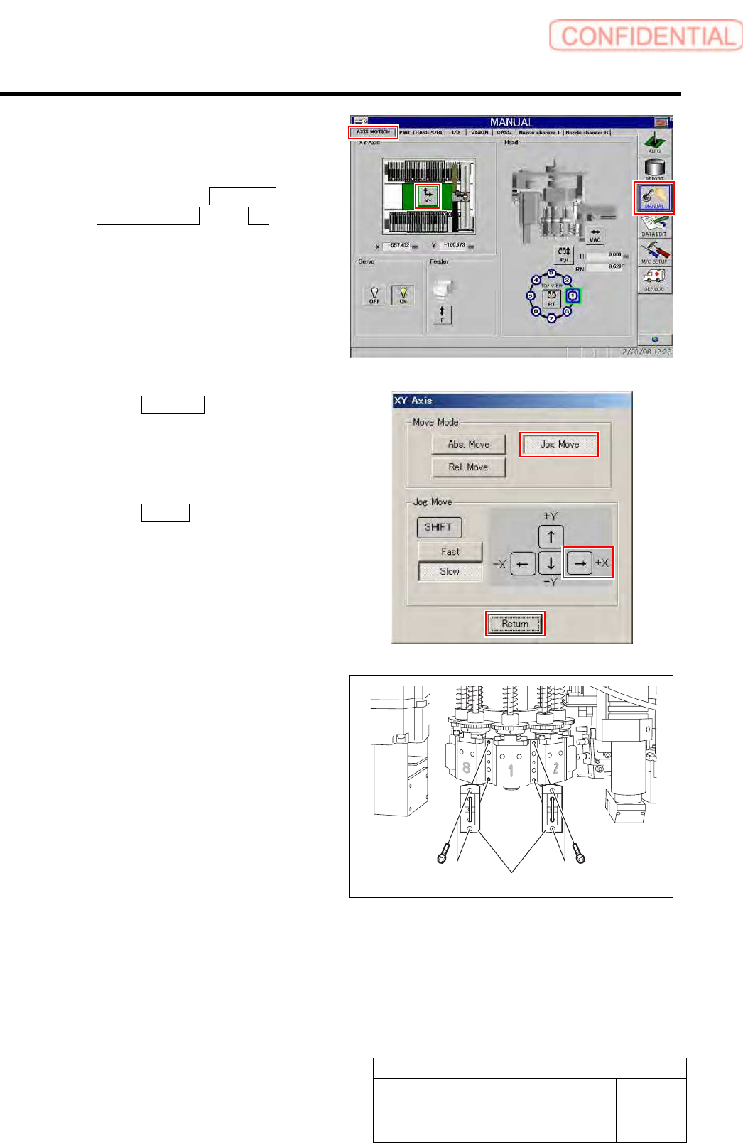
2 Move the head to a position by manual
operation where working can be easily
performed.
1. Click in an order of MANUAL menu
AXIS MOTION tab XY button.
XY Axis screen is displayed.
2. Click the Jog Move button in the move
mode.
3. Press the right cursor to jog-move the
head to vicinity of No.120 of head
supply part.
4. Click the Return button to close the
XY Axis screen.
3 Remove the mechanical valve.
1. Loosen CP-3x10 to remove the
mechanical valves for Index 1 and
Index 2.
Mechanical valve
Adjustment
HLGB-10414-01
Phase Adjustment for Nozzle
SHEET
3/7
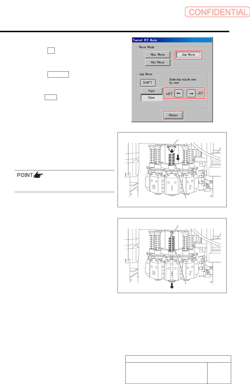
4 Remove the inner shaft for turret No.1.
1. Click the RT button on the Axis
MOTION screen.
Turret RT Axis screen is displayed.
2. Click the Jog Move button.
3. Press the left and right cursor key to
move the turret No.1 to the front.
Click the Return button to close the Turret RT
Axis screen.
4. Turn the notch on the spring holder to
deep side.
5. Pull the spring holder toward you with
the spring being lowered down to
remove the spring holder.
Be careful to prevent the inner shaft from
falling.
6. Remove the spring.
7. Pull out the inner shaft from lower
side of the head.
5 Press the emergency stop switch to turn off
the servo.
Spring holder
Spring
Spring
Inner shaft
Adjustment
HLGB-10414-01
Phase Adjustment for Nozzle
SHEET
4/7
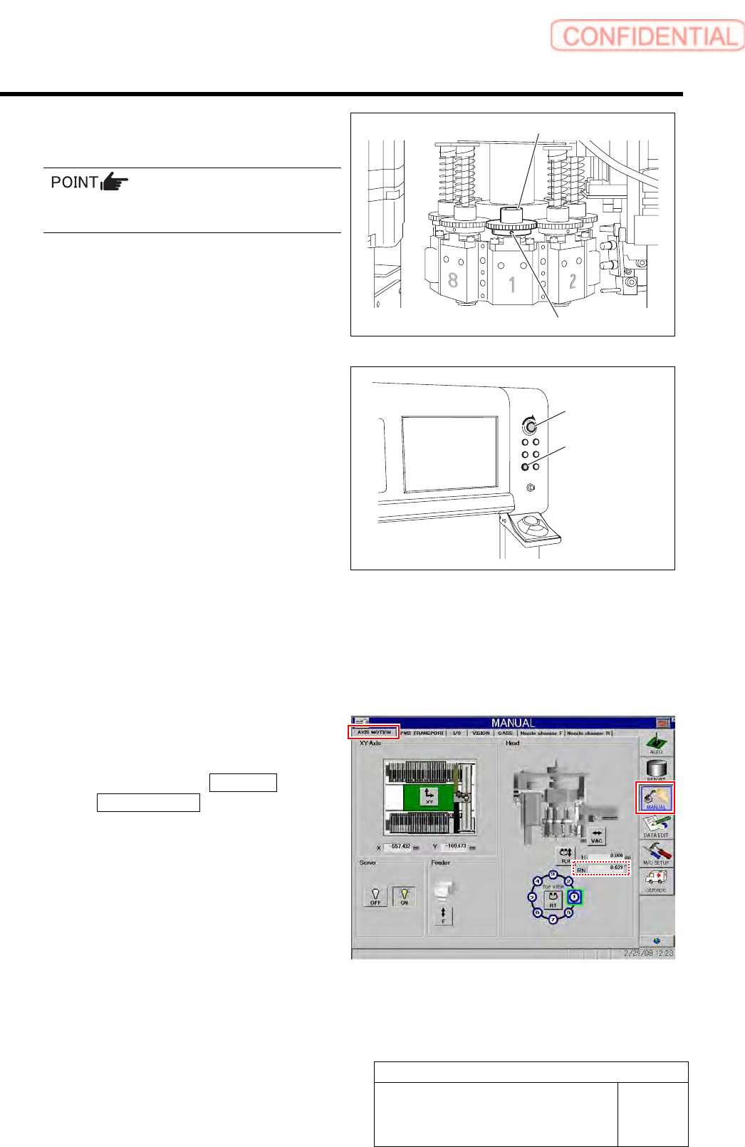
6 Loosen the set screws (2-H2.5x4) fixing the
small gear for the turret No.1.
Do not remove the set screw fixing the small
gear. Otherwise, the set shoe may fall.
7 Release emergency stop to return the unit to
the origin.
1. Turn the emergency stop switch to
release emergency stop.
2. Click the [ORG] button to return the
system to the original position.
8 Again move the head to a position where
working can be easily performed.
9 Operate the turret RT axis screen to move
the turret No.1 toward you.
10 Adjust the direction of the set screw for the
small gear.
1. Click in an order of MANUAL menu
AXIS MOTION tab.
AXIS MOTION screen is displayed.
2. Check that current position of the RN
axis is 0°.
Emergency stop
switch
ORG button
Set screw
Small gear