MAN00000772_SI-G200BB_SVCPDFA.pdf - 第606页
Alarm List for the Servo Pack "S igma-III" Series (SGDS type) BBGB-10101-01 Alarm List for the Servo Pack "Sigma-III" Series (SGDS type) SHEET 17/18 Mode Selection The digital o perator has four displ…
Alarm List for the Servo Pack "Sigma-III" Series (SGDS type)
BBGB-10101-01
Alarm List for the Servo Pack
"Sigma-III" Series (SGDS type)
SHEET
16/18
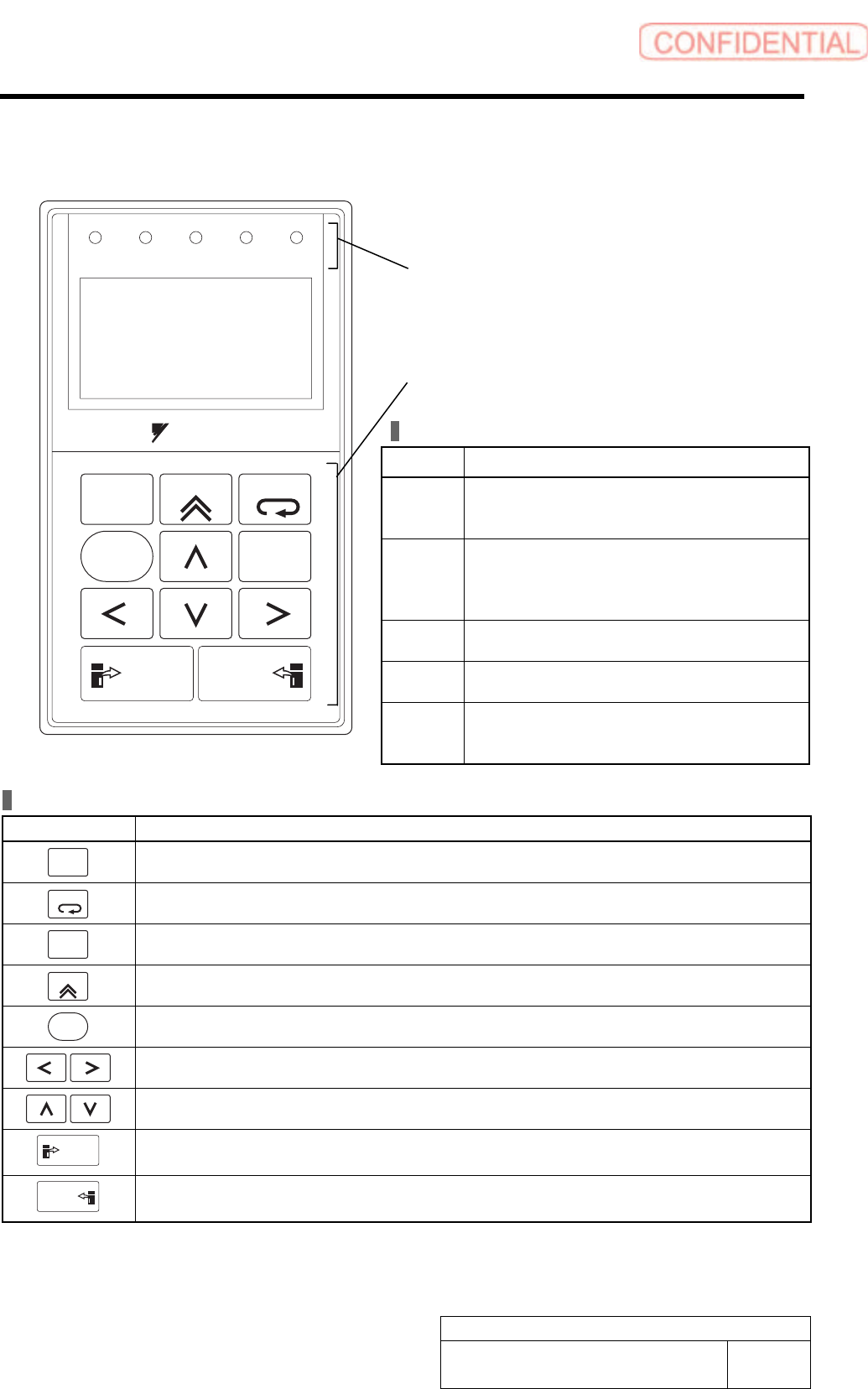
Part Names and Functions
LED Indicator Lamps
Name Function
SVON Lit when the servo is ON.
Unlit at base block (when the power to the
servomotor is OFF.).
COIN
VCMP
Lit when positioning is completed.
Unlit when positioning is not completed.
Lit when the speed is coincident.
Unlit when the speed is not coincident.
IGON Lit while the servomotor is running.
Unlit while the servomotor stops running.
REF Lit when the reference pulse is input.
Unlit when the reference pulse is not input.
CHARGE Lit when the main circuit power supply is ON.
Unlit when the main circuit power supply is
OFF.
ALARM
RESET
SCROLL
YASKAWA
MODE/SET
JOG
SVON
READ
SERVO
DATA
WRITE
SERVO
SVCN TGON REF
CHARGE
COIN
VCMP
Operation Keys
Operation Key Main Function
ALARM
RESET
Resets the alarm. (The alarm cannot be reset unless the cause of the alarm is removed.)
MODE/SET
Switches the Display Mode of digital operator.
DATA
Switches the cursor position between the parameter number and the setting when setting a
parameter. Opens the selected utility function display in Utility Function Mode.
SCROLL
Moves the cursor upward in Parameter/Monitor Mode.
JOG
SVON
Turns the servo ON or OFF at JOG operation.
Moves the cursor to left or right in Parameter/Monitor Mode.
Increases or decreases the parameter number, setting data, monitor number, and utility
function number. Or, rotates the servomotor in forward or reverse direction at JOG operation.
READ
SERVO
Reads parameters saved in the SERVOPACK to the digital operator.
WRITE
SERVO
Saves the display in Parameter/Monitor Mode, JOG operation, and Origin Search.
LED indicators
(Five LED indicator lamps in red)
Operation keys
LCD display
(17 characters × 5 lines)
Alarm List for the Servo Pack "Sigma-III" Series (SGDS type)
BBGB-10101-01
Alarm List for the Servo Pack
"Sigma-III" Series (SGDS type)
SHEET
17/18
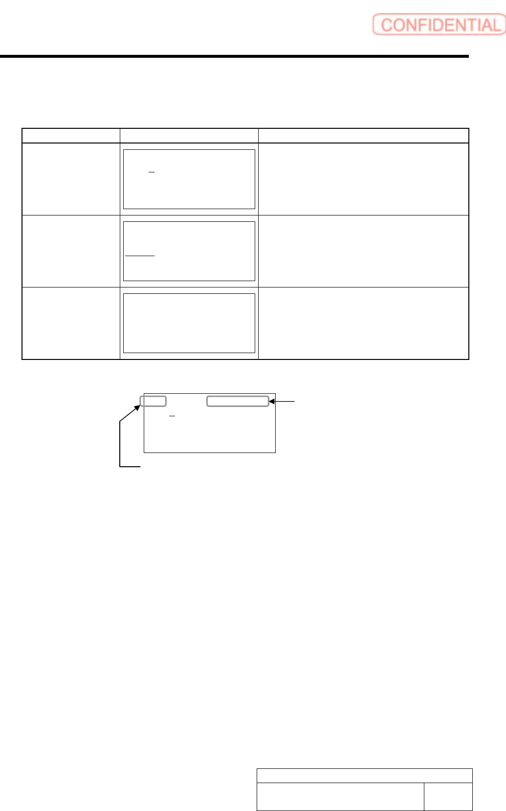
Mode Selection
The digital operator has four display modes:
Mode Display Example
*1
Function
Parameter
/Monitor Modes
BB -PRM/MON-
Un000= 00000
Un002= 00000
Un008= 00000
Un00D=00000000
Displays the monitor item Un.
Displays and set a parameter Pn.
Utility Function
Mode
BB -FUNCTION-
Fn00E
Fn000
Fn001
Fn002
Executes a utility function Fn.
*2
Alarm Display
BB -ALARM-
0:D00 00001207196
1:720 00000032651
2:511 00000009043
3:---
Displays the alarm traceback data.
The latest 10 alarms are displayed with type
stamp.
*1 The abbreviation of each mode is displayed on the right top, and the SERVOPACK status is displayed
on the left top.
BB -PRM/MON-
Un000= 00000
Un002= 00000
Un008= 00000
Un00D=00000000
Mode
-PRM/MON- : Parameter/Monitor Modes
-FUNCTION- : Utility Function Mode
-ALARM- : Alarm Display
Status
BB : Base blocked
RUN : Servomotor is ON
A.*** : The alarm occurs (***: Alarm code)
PT NT : Forward run and reverse run prohibited (Over travel)
P-OT : Forward run prohibited (Over travel)
N-OT : Reverse run prohibited (Over travel)
NO-OP : Setting disabled or setting error
*2 Utility Function Fn
• Alarm traceback data display
• JOG mode operation
• Program JOG operation
• Clear alarm traceback data
• Absolute encoder multi-turn reset and encoder
alarm reset
• Manual zero adjustment/Manual gain
adjustment of analog monitor output
• Write prohibited setting
• Software version display
• One-parameter autotuning for less deviation
• One-parameter autotuning
• Online vibration monitor
• SERVOPACK and servomotor ID display
• Rigidity setting during normal autotuning
• Origin search mode
• Initialize parameter settings
• Save moment of inertia ratio data obtained from
normal autotuning
• Automatic/Manual adjustment of analog
reference offset
• Automatic/Manual offset-adjustment of motor
current detection signal
• Check servomotor models
• Multi-turn limit value setting change when a
Multi-turn Limit Disagreement alarm occurs
• Advanced autotuning
• EasyFFT
• Initialize vibration detection level
Alarm List for the Servo Pack "Sigma-III" Series (SGDS type)
BBGB-10101-01
Alarm List for the Servo Pack
"Sigma-III" Series (SGDS type)
SHEET
18/18
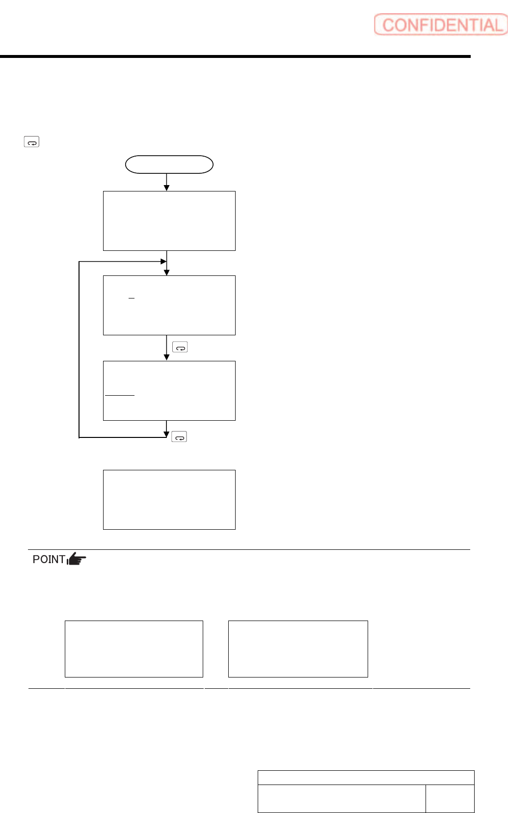
Switching Mode
Connect the digital operator to the SERVOPACK, and turn ON the power to the SERVOPACK.
The initial display appears, and then the Parameter/Monitor Mode display appears. Press the
MODE/SET
Key to change the mode. When an alarm occurs, the alarm display appears automatically.
File list loading
Please wait….
[Initial Display]
Displayed for two seconds
BB -PRM/MON-
Un000= 00000
Un002= 00000
Un008= 00000
Un00D=00000000
[Parameter/Monitor Modes]
MODE/SET
BB -FUNCTION-
Fn01E
Fn000
Fn001
Fn002
[Utility Function Mode]
MODE/SET
A.D00 -ALARM-
0:D00 00001207196
1:720 00000032651
2:511 00000009043
3:---
[Alarm Display]
When an alarm occurs, the alarm display appears
automatically.
If a communications error occurs between the SERVOPACK and digital operator, the following
communications error codes are displayed. These errors may be caused by incorrect connector
connection. Check the connection and correct. Then, turn the power OFF and ON. If the error
still occurs, replace the digital operator or the SERVOPACK.
CPF00
COM-ERR(OP&SV)
CPF01
COM-ERR(OP&SV)
* For detail of how to operate Digital Operator, refer to the “Instruction Manual for Sigma-III
Series SGMS/SGDS Digital Operator” in separate volume.
Power ON