MAN00000772_SI-G200BB_SVCPDFA.pdf - 第163页
Preparation for Calibration HLGB-10105-01 Calibration Dat a Load SHEET 1/3 Calibration Dat a Load [Necessary jigs] • Calibration d ata FD [Procedure] 1 Record the description in the existing ca lib.ini. < When perform…
Preparation for Calibration
HLGB-10104-01
Change in User Level
SHEET
1/1
Change in User Level
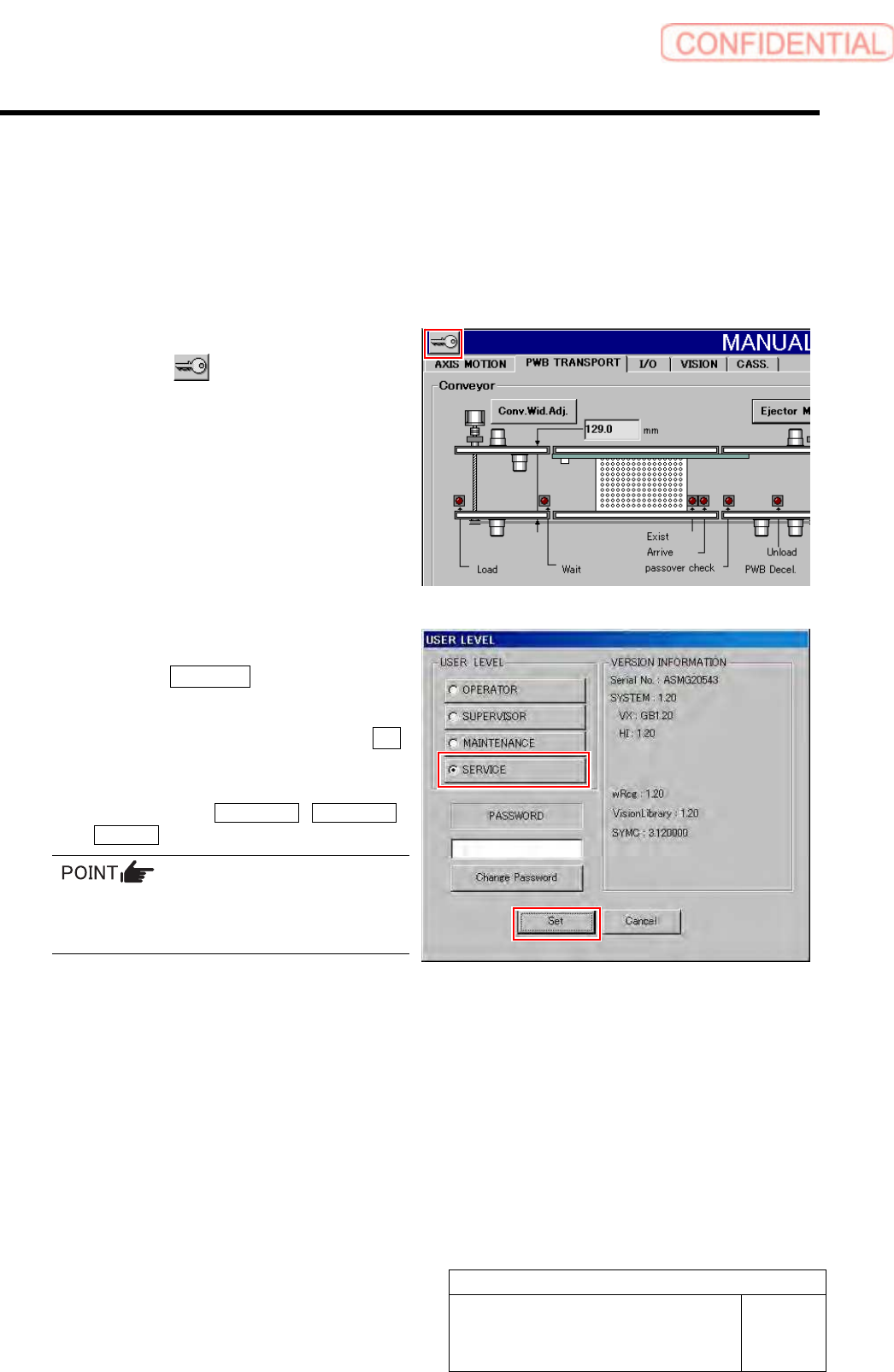
To display a screen used for calibration, it is necessary to change user level. This section describes a
procedure to change user level.
[Procedure]
1 Display the USER LEVEL screen.
1. Click the
button on the left
upper of the screen.
USER LEVEL screen is displayed.
2 Change the USER LEVEL to “SERVICE”.
1. Click the SERVICE button.
A cursor appears on a PASSWORD entry space.
2. Enter the password and click the Set
button.
The screen returns to HI screen and respective
menu buttons of DATA EDIT, M/C SETUP,
SERVICE appear on the right of the screen.
To display the calibration screen, it is necessary
to change the USER LEVEL to
[MAINTENANCE] or [SERVICE].
Preparation for Calibration
HLGB-10105-01
Calibration Data Load
SHEET
1/3
Calibration Data Load
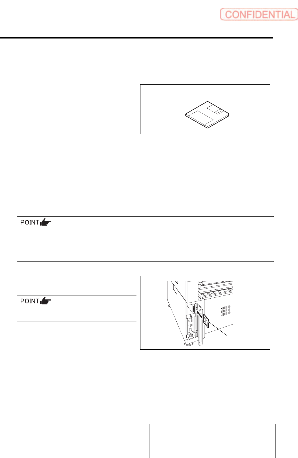
[Necessary jigs]
• Calibration data FD
[Procedure]
1 Record the description in the existing calib.ini.
< When performing calibration for the front head >
Record a value of MOUNT_HEIGHT,FIXED_INSP_HEIGHT in “c:¥asm¥mcdata1¥head.ini”.
< When performing calibration for the front head >
Record a value of MOUNT_HEIGHT,FIXED_INSP_HEIGHT in the “c:¥asm¥mcdata2¥head.ini”.
If there’s no description in Calib.ini, refer to the following.
Same value as MOUNT_HEIGHT in NOZZLE_S_TYPE_G = head.ini
A value obtained by subtracting “3” from MOUNT_HEIGHT in NOZZLE_T_TYPE_G = head.ini
A value of H of [FixedCamera] POS_XYH in FIXED_INSP_HEIGHT = head.ini
2 Set a FD including calibration plate
data(calib.ini) into the FD drive of the unit.
Use a FD having a same No as the ball point
jig.
Calibration data FD
Calibration data FD
Preparation for Calibration
HLGB-10105-01
Calibration Data Load
SHEET
2/3
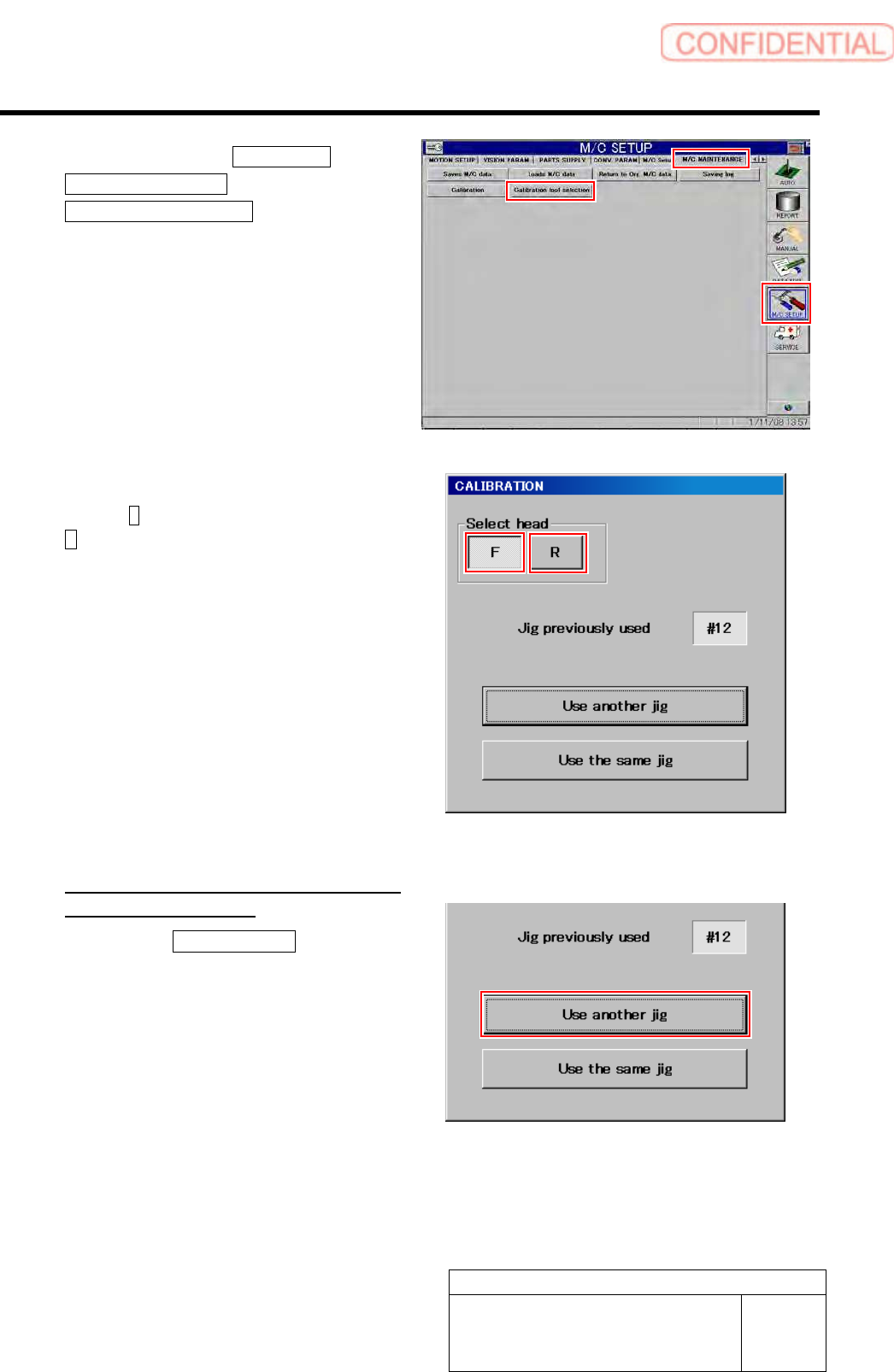
3 Click in an order of M/C SETUP menu
M/C MAINTENANCE tab
Calibration tool selection button.
A select screen for jig used for calibration appears.
4 Select head to be calibrated.
Press the F button for the front head, and press the
R for the rear head.
5 Select jig used for calibration.
<When the indicated jig No is different
form jig No to be used>
1. Press the Use another jig button.
Calibration plate data is read into the unit, and jig
select screen is closes.