MAN00000772_SI-G200BB_SVCPDFA.pdf - 第231页
Calibration HLGB-10308-01 Pickup Check Camera Calibration SHEET 1/5 Pickup Check Camera Calibration Perform this working on both heads on the front sid e and rear side. [Necessary jigs] A Calibration data FD B Calibratio…
Calibration
HLGB-10307-01
Nozzle Changer Teaching
SHEET
5/5
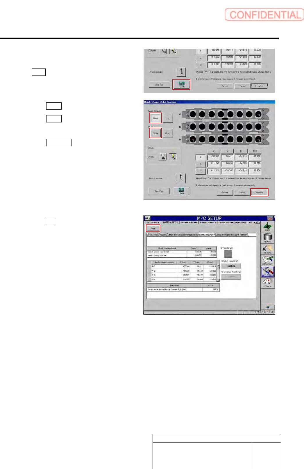
14 When the coordination of the three positions
(A-1, A-8, and C-8) has been acquired, click
the Calc. button.
Coordinate of the other nozzle replacing positions are
calculated based on coordinates on three locations.
15 Click the Close button to close the shutter.
16 Click the Down button to lower the nozzle
changer.
17 Click the Complete button to exit the
Teaching window.
18 Click the Set button on the MOTION SETUP
screen.
Coordinate of nozzle replacement position is set to the
unit.
19 Remove the jig nozzle and end operation of
nozzle changer teaching.
Calibration
HLGB-10308-01
Pickup Check Camera Calibration
SHEET
1/5
Pickup Check Camera Calibration
Perform this working on both heads on the front side and rear side.
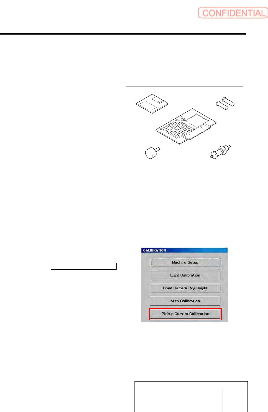
[Necessary jigs]
A Calibration data FD
B Calibration plate jig
C Jig positioning pin
D Pickup check resolution inspection jig B
E Length reference nozzle jig
[Procedure]
1 Load the calibration data.
For calibration data loading procedure, refer to “Calibration Data Load [HLGB-10105-01]”.
2 Install the calibration plate jig.
For calibration plate installation procedure, refer to “Install the Calibration Plate Jig [HLGB-10101-01]”.
3 Display a Pickup Camera Calibration
screen.
1. Click the Pickup Camera Calibration
button on the CALIBRATION screen.
Pickup Camera Calibration screen is displayed.
A
B
C
D
E
Calibration
HLGB-10308-01
Pickup Check Camera Calibration
SHEET
2/5
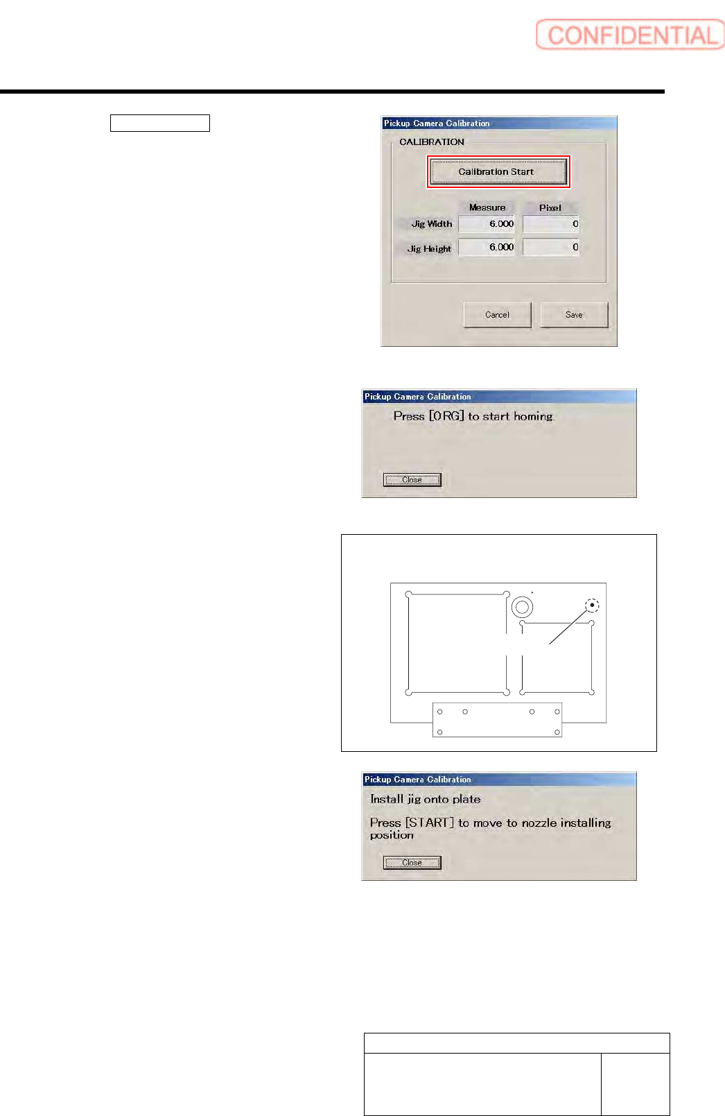
4 Click the Calibration Start button.
“Press [ORG] button to start homing” is displayed on
the message screen.
5 Press the [ORG] button on the operation
panel.
Origin position return is performed and “Install jig
onto plate” is displayed on the message screen.
6 Set a detection resolution check jig into the
insertion hole on the calibration plate jig, and
press the [START] button on the operation
panel.
Head portion moves to the jig setup position, and
“Install nozzle for pickup inspection to index 1” is
displayed on the message screen.
Calibration plate upper surface figure
Insertion hole