MAN00000772_SI-G200BB_SVCPDFA.pdf - 第337页
Adjustment HLGB-10415-01 Nozzle Sensor Adjus tment SHEET 5/7 [Threshold value setting for sensor] Set the threshold value after the XY co ordinate for the nozzle has been set. 1 Move the head to a better position to work…
Adjustment
HLGB-10415-01
Nozzle Sensor Adjustment
SHEET
4/7
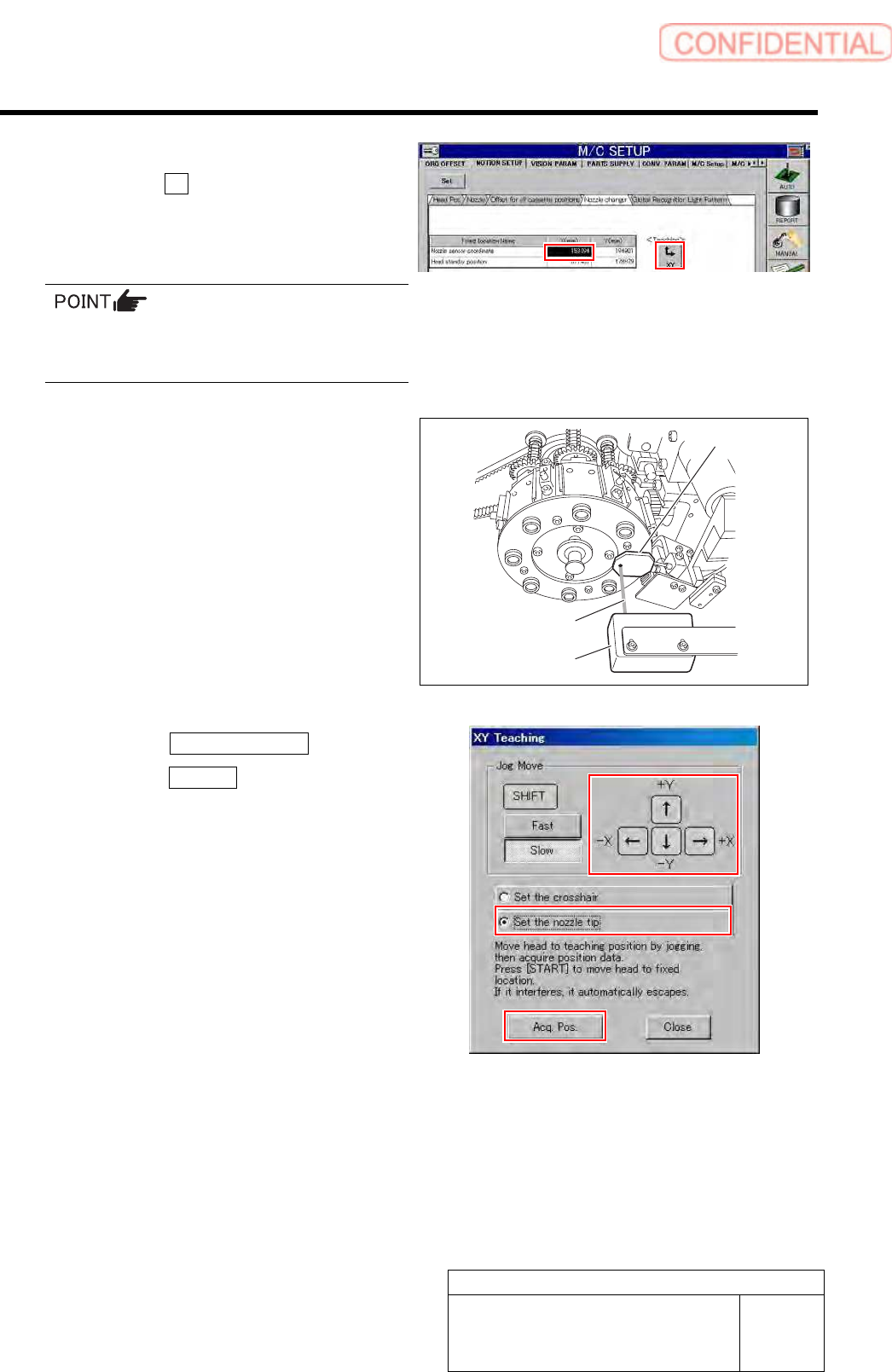
4 Select a nozzle sensor coordinate space
and click the XY button for teaching.
XY teaching screen is displayed.
If the Teaching button does not become enabled,
click on the “Nozzle sensor coordinate” column
and then click the Teaching button again.
5 Acquire coordinate at a position where black
dot on the back of the jig nozzle is aligned
with opticl axis of the nozzle sensor.
1. Operate the XY Teaching window to
align the light axis of the sensor and
the black dot on the bottom of the jig
nozzle.
2. Click the Set the nozzle tip button.
3. Click the Acq Pos. button.
Coordinate of the current position is acquired.
6 Move the head to a better position to work
with, and then remove the jig nozzle.
Opticl axis
Nozzle sensor
Jig nozzle
Adjustment
HLGB-10415-01
Nozzle Sensor Adjustment
SHEET
5/7
[Threshold value setting for sensor]
Set the threshold value after the XY coordinate for the nozzle has been set.
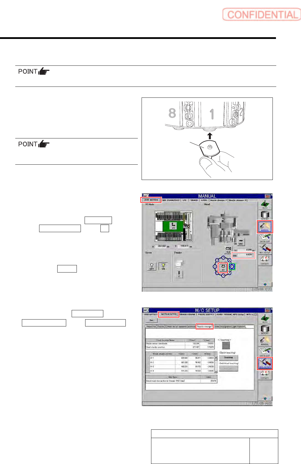
1 Move the head to a better position to work
with, and then attach the nozzle to turret No.
1.
Attach the nozzle used in the production process
(do not attach the jig nozzle).
2 Move the turret No.1 to under the H-axis and
make sure that the RN-axis is 0 degrees.
1. Click in an order of MANUAL menu
AXIS MOTION tab RT button.
Turret RT Axis screen is displayed.
2. Operate the RT axis screen and move
the turret No.1 down to the H axis.
3. Click the Return button to close the
Turret RT Axis screen.
4. Check that angle of the RN axis is 0°
on the axis operation screen.
3 Click in an order of M/C SETUP menu
MOTION SETUP tab Nozzle changer
tab.
Nozzle changer screen is displayed.
Nozzle
Adjustment
HLGB-10415-01
Nozzle Sensor Adjustment
SHEET
6/7
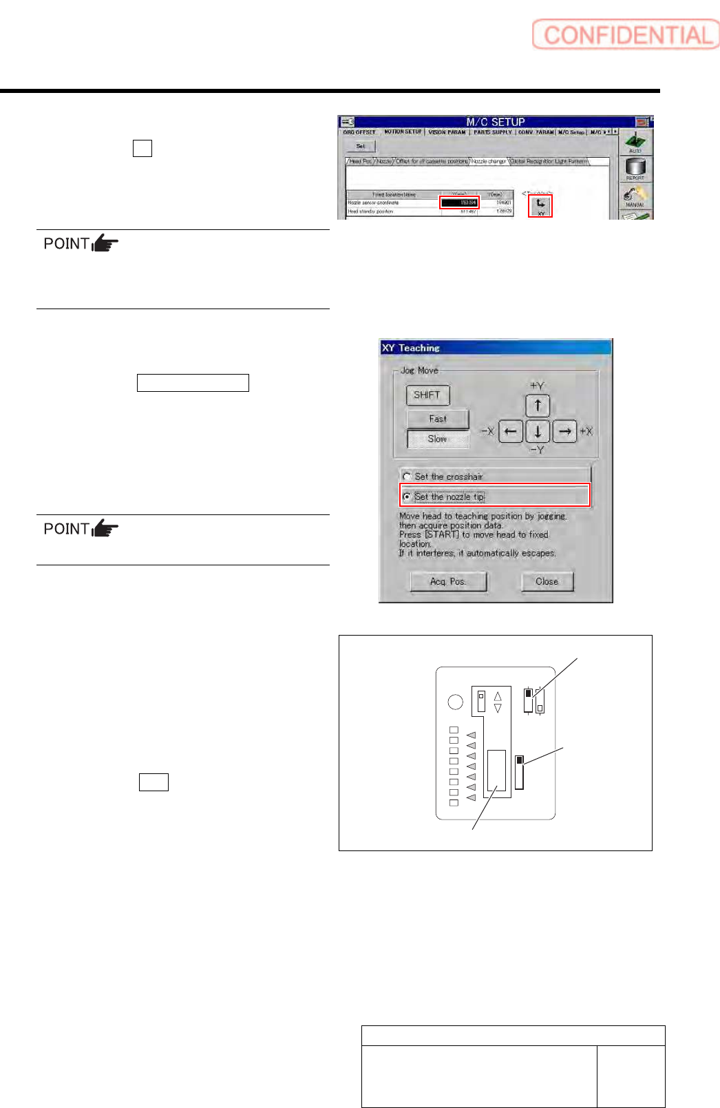
4 Select a nozzle sensor coordinate space
and click the XY button for teaching.
XY teaching screen is displayed.
If the Teaching button does not become enabled,
click on the “Nozzle sensor coordinate” column
and then click the Teaching button again.
5 Move the head to the set teaching position.
1. Click the Set the nozzle tip button.
2. Press the [START] button on the
operation panel.
The head moves to the currently set position.
Do not click the Acq. Pos. button.
6 Set a threshold value with the nozzle sensor.
1. Open the sensor cover.
2. Set the mode set switch to TEACH.
3. Check that the NORM/ZONE switch is
set to NORM.
4. Press the SET button.
The LEDs from NEAR to FAR turn on red.
OUT
SET
NORM
TEACH
RUN
ADJ
ZONE
L
D
NEAR
FAR
NORM/ZONE switch
Mode set
switch
SET button