MAN00000772_SI-G200BB_SVCPDFA.pdf - 第230页
Calibration HLGB-10307-01 Nozzle Changer T eaching SHEET 5/5 14 When the co ordination of the three positions (A-1, A-8, an d C-8) has been acquired, click the Calc. button. Coordinate of the other no zzle replacing posi…
Calibration
HLGB-10307-01
Nozzle Changer Teaching
SHEET
4/5
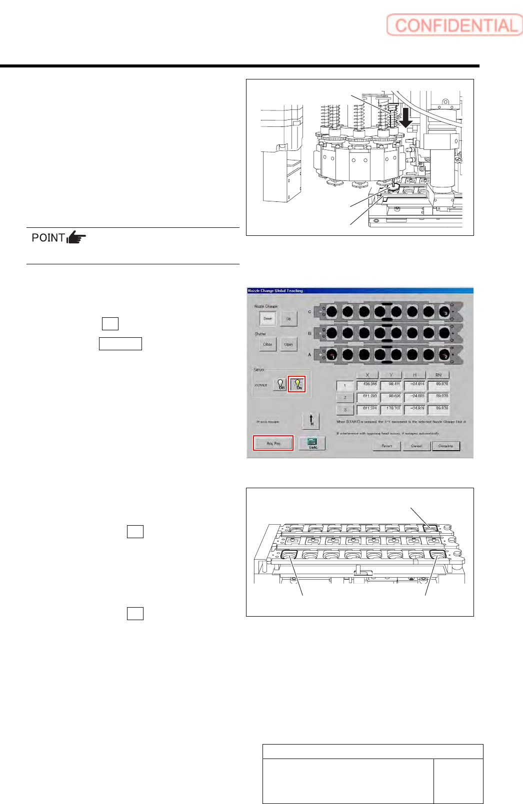
12 Capture coordinate of nozzle replacing
position.
1. Move the head manually so that the
jig nozzle of turret No.1 comes above
A-1 of the nozzle changer.
2. Lower the inner shaft with your finger
and make sure the jig nozzle can be
inserted into the nozzle cartridge A-1
smoothly.
Position the X, Y, and RN axes accurately.
3. While keeping the H-axis in the
lowered position with your finger, turn
the Servo ON.
4. Click the Acq. Pos. button.
13 In a like manner, acquire the coordination of
the nozzle positions for A-8 and C-8.
1. Make sure the 2 button is pressed,
and then turn the Servo OFF.
2. Capture A-8 replacing position
coordinate by the same procedure as
the procedure 12.
3. Make sure the 3 button is pressed,
and then turn the Servo OFF.
4. Capture C-8 replacing position
coordinate by the same procedure as
the procedure 12.
Inner shaft
Jig nozzle
Nozzle cartridge
C-8
A-8
A
-1
Calibration
HLGB-10307-01
Nozzle Changer Teaching
SHEET
5/5
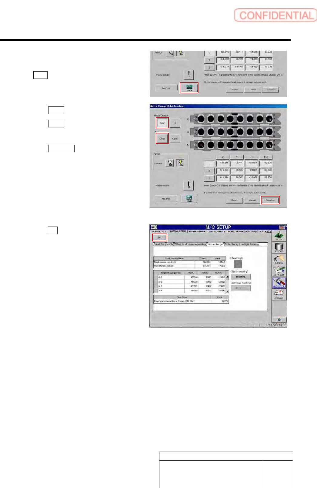
14 When the coordination of the three positions
(A-1, A-8, and C-8) has been acquired, click
the Calc. button.
Coordinate of the other nozzle replacing positions are
calculated based on coordinates on three locations.
15 Click the Close button to close the shutter.
16 Click the Down button to lower the nozzle
changer.
17 Click the Complete button to exit the
Teaching window.
18 Click the Set button on the MOTION SETUP
screen.
Coordinate of nozzle replacement position is set to the
unit.
19 Remove the jig nozzle and end operation of
nozzle changer teaching.
Calibration
HLGB-10308-01
Pickup Check Camera Calibration
SHEET
1/5
Pickup Check Camera Calibration
Perform this working on both heads on the front side and rear side.
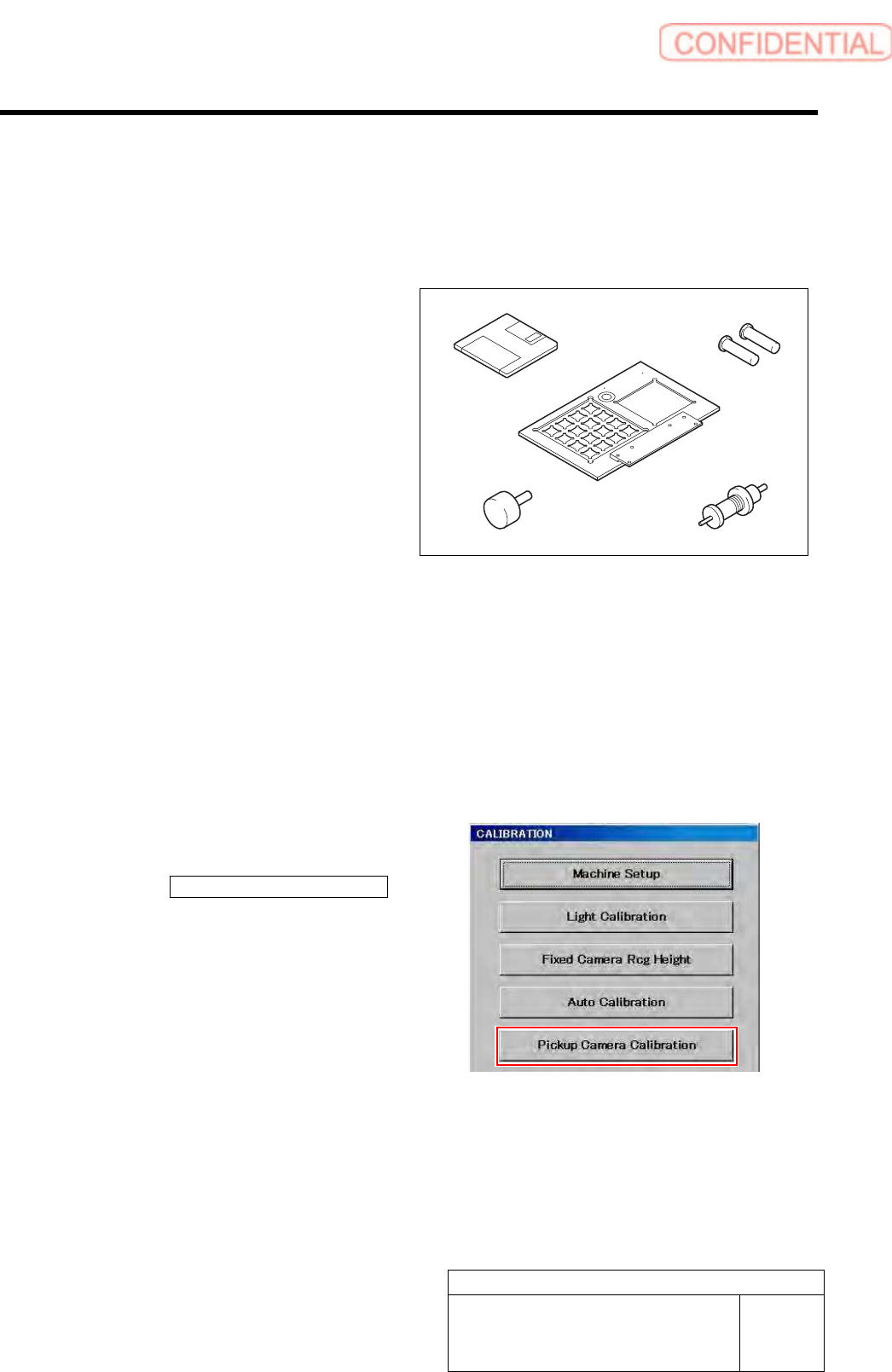
[Necessary jigs]
A Calibration data FD
B Calibration plate jig
C Jig positioning pin
D Pickup check resolution inspection jig B
E Length reference nozzle jig
[Procedure]
1 Load the calibration data.
For calibration data loading procedure, refer to “Calibration Data Load [HLGB-10105-01]”.
2 Install the calibration plate jig.
For calibration plate installation procedure, refer to “Install the Calibration Plate Jig [HLGB-10101-01]”.
3 Display a Pickup Camera Calibration
screen.
1. Click the Pickup Camera Calibration
button on the CALIBRATION screen.
Pickup Camera Calibration screen is displayed.
A
B
C
D
E