MAN00000772_SI-G200BB_SVCPDFA.pdf - 第157页
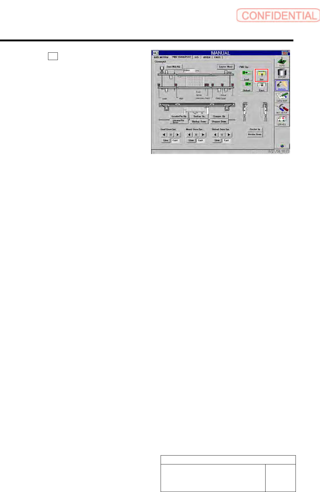
Preparation for Calibration HLGB-10101-01 Install the Calibration Plate Jig SHEET 3/3 5 Click the Set button to fix the calibration plate. 6 Release the emergency stop switch to return the unit to the origin.
Preparation for Calibration
HLGB-10101-01
Install the Calibration Plate Jig
SHEET
2/3
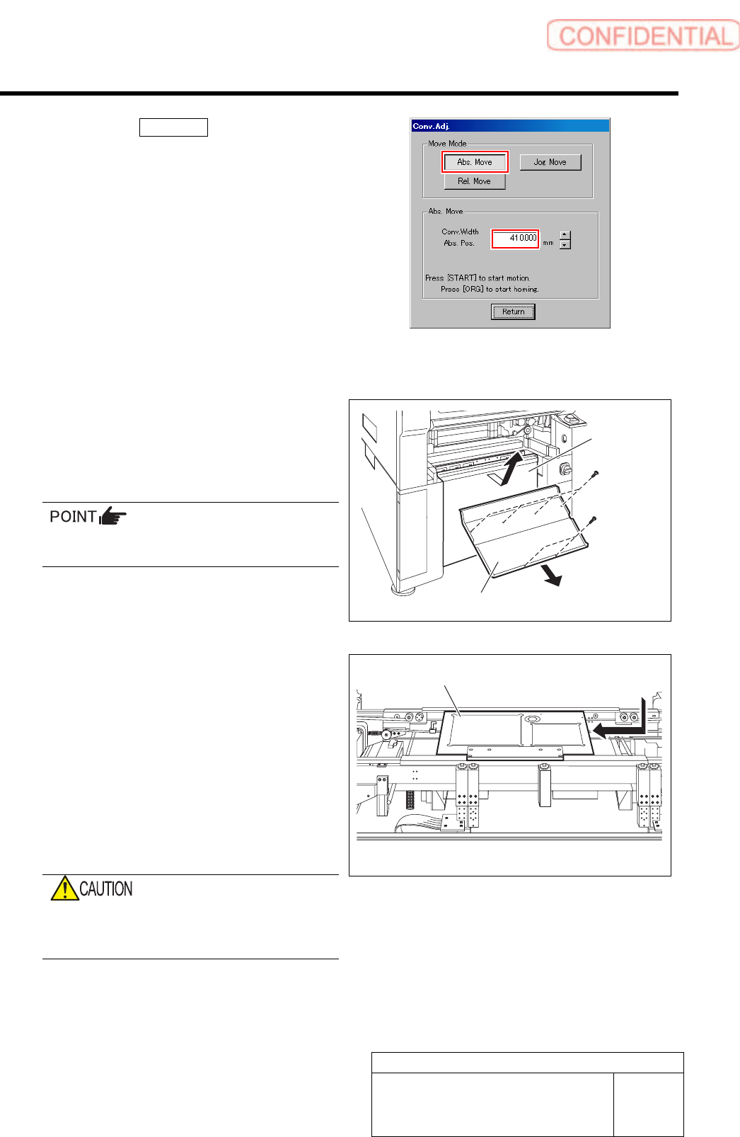
2. Click the Abs. Move button on the
Conv. Adj. screen.
3. Input “186” into the input box of the
Conv. Width Abs. Pos.
4. Press the [START] button on the
operation panel.
Conveyor width is widened to the position of 186
mm.
2 Press the emergency stop button to turn
OFF the servo.
3 Remove the lower cover and shooter on the
front of the unit.
1. Loosen screw (2-+T4x8) to remove the
lower cover.
Tile the lower cover slightly toward you and
pull the fan cable to remove the lower panel.
2. Loosen screw (2-+T4x8) to remove the
shooter.
4 Install the calibration plate jig.
1. Place the calibration plate jig on the
rail on the right of the conveyor and
slide it to near the center of the
conveyor.
2. Insert the jig positioning pins (two)
into the calibration plate jig.
3. Remove the cap screw for jig
positioning pin.
If the cap screw for the jig positioning pin is
forgotten to be pulled out, it may interfere
with the head, causing damage on the unit.
Calibration plate jig
Lower cover
Shooter
Preparation for Calibration
HLGB-10101-01
Install the Calibration Plate Jig
SHEET
3/3
5 Click the Set button to fix the calibration
plate.
6 Release the emergency stop switch to return
the unit to the origin.
Preparation for Calibration
HLGB-10102-01
Remove Production Nozzle
SHEET
1/1
Remove Production Nozzle
Remove the nozzle used for production according to the procedure in this section because it is not
used for calibration operation.
[Procedure]
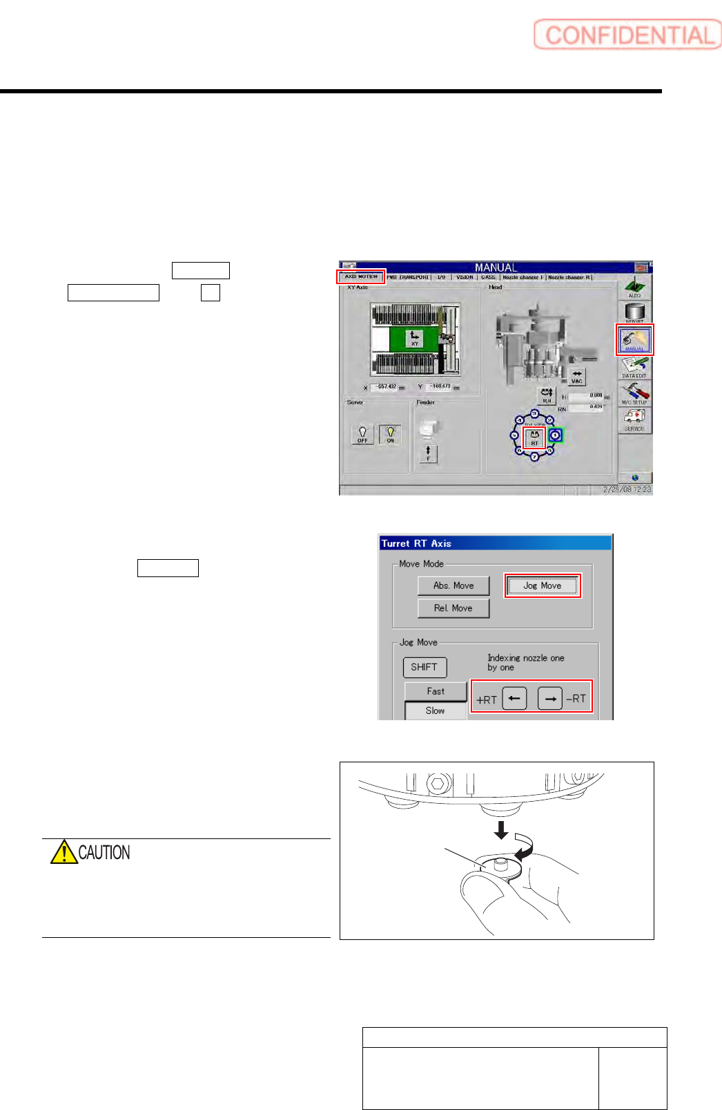
1 Click in an order of MANUAL menu
AXIS MOTION tab RT button.
Turret RT Axis screen is displayed.
2 Move the nozzle to be removed toward you.
1. Click the Jog Move button in the move
mode.
2. Press the cursor key on the left and
right to jog move the nozzle to be
removed toward you.
3 Grab circumference of the nozzle by fingers
and pull out downward with light force while
turning the nozzle slowly.
When removing the nozzle, do not grab the
end of the nozzle.
Otherwise, the nozzle may be deformed,
causing failure of adsorption or placement.
4 Repeat the procedure 2 and 3 to remove all
of the 8 nozzles.
Nozzle