MAN00000772_SI-G200BB_SVCPDFA.pdf - 第248页
Calibration HLGB-1031 1-01 Pickup Position Setup SHEET 4/9 [XY Position Dat a T e aching] 1 Click #1 and input “106” in the input box for T ool Located Cass. 2 Light up the PWB camera light. 1. Click the ON button on th …
Calibration
HLGB-10311-01
Pickup Position Setup
SHEET
3/9
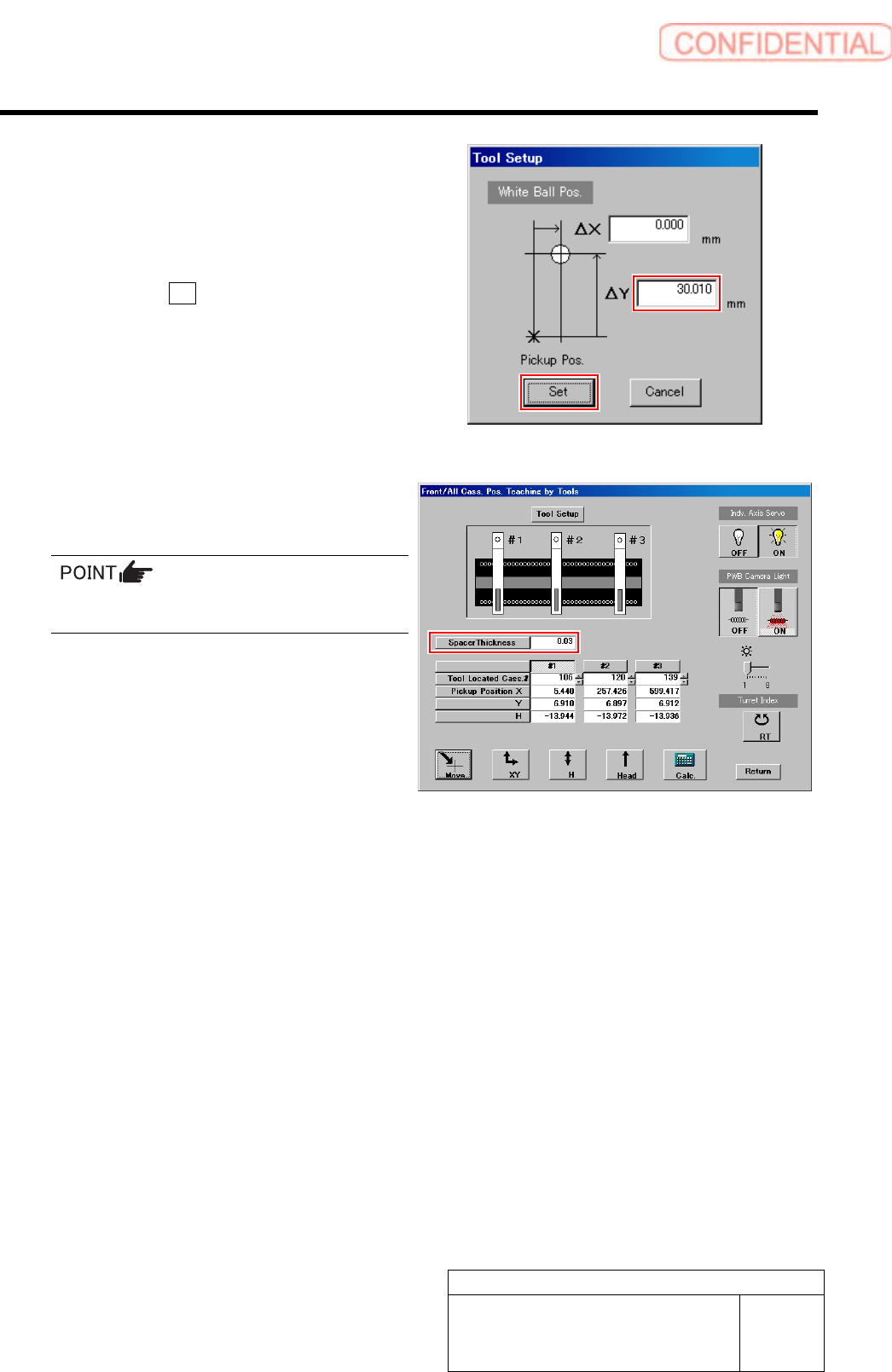
2. Check jig information (ΔY) attached
on the side of the pickup point jig.
3. Enter value ofΔY written on the side
of the pickup point jig into the ΔY box
on the jig setting screen.
4. Click the Set button.
The value of ΔY is set and the jig setting screen
is closed.
5. Input thickness of “0.03” of thickness
gauge used for H axis position data
teaching.
The value of the spacer thickness becomes
offset value when acquiring H coordinate.
Calibration
HLGB-10311-01
Pickup Position Setup
SHEET
4/9
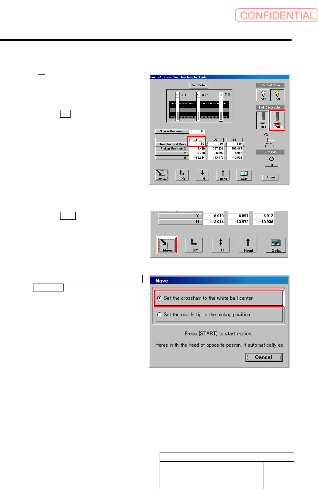
[XY Position Data Teaching]
1 Click #1 and input “106” in the input box for
Tool Located Cass.
2 Light up the PWB camera light.
1. Click the ON button on the PWB
camera light.
The PWB camera light lights up.
2. Set brightness of the PWB camera
light to “6” or “7”.
3 Move the PWB camera to the pickup point.
1. Click the Move button.
Move screen is displayed.
2. Click the Set the crosshair to the white
ball center button.
3. Press the [START] button on the
operation panel.
The PWB camera automatically moves to nearly
the center of the pickup point.
Hole on the pickup point jig is displayed on the
PARTS DISPLAY window at this time.
Calibration
HLGB-10311-01
Pickup Position Setup
SHEET
5/9
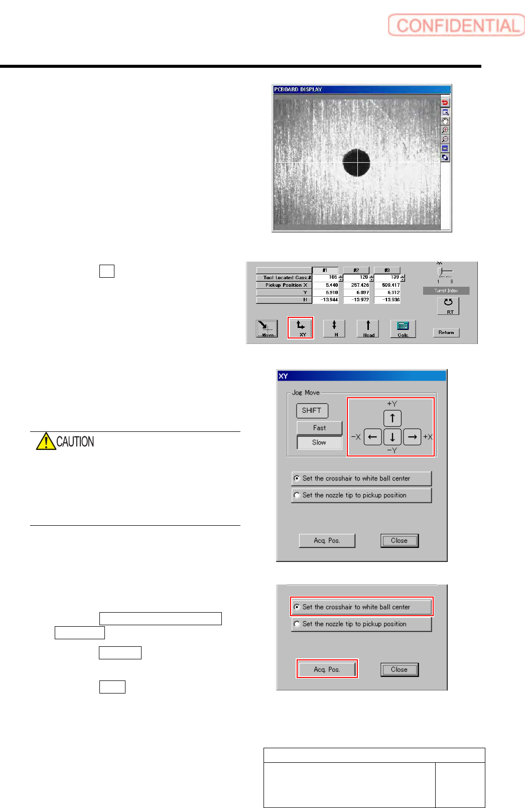
4 Set the cross hairline to the pickup point
while checking the PARTS DISPLAY
window.
1. Click the XY button on the Front/All
Cass. Pos. Teaching by Tools screen.
XY screen is displayed.
2. Press the cursor key to jog move the
head until the hole in the end of the
pickup point jig is positioned on the
crosshair on the PARTS DISPLAY.
When checking on the PARTS DISPLAY with
the screen being small, discrepancy of hole
center may not be found.
Be sure to expand the window of the PARTS
DISPLAY to enlarge the displayed image and
check the hole center.
5 Acquire the XY position after positioning.
1. Click the Set the crosshair to white
ball center button.
2. Click the Acq. Pos. button on the XY
screen to acquire XY position.
3. Click the Close button to close the XY
screen.