MAN00000772_SI-G200BB_SVCPDFA.pdf - 第669页
Ch ange Procedu re for RN Axis Mo to r U n i t Change Pro cedure fo r RN Axis Motor Unit [Necess a r y Jigs] Te nsion Mete r (UNIT T A U-507) Be lt Tensio n Jig (For B) [Disassembly] 1 Open the f ront and re ar slide do …
Change Procedure for PWB Camera
[Reassembly]
3 Attach the PWB Camera (B) Assy
1. Put PWB Camera (B) Assy between Camera support.
2. Temporarily tighten the screws(2-C4x18).
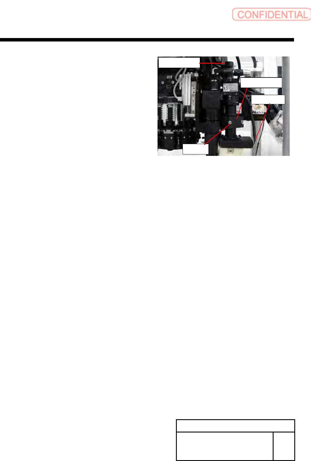
4 Attach the PWB Camera cable.
1.Camera cable
2.LED cable
[Adjustment]
5 Calibration
1.HLGB-10204-01 PWB Camera Setup
2.HLBG-10205-01 Fiducial Mark Setup
3.HLBG-10101-01 Preparation for Calibration
4.HLBG-10301-01 Calibration
Change Procedure for Board
Camera
RPGB-10401-1
SEET
2/2
Camera cable
C4x18
Camera support
LED cable
Change Procedure for RN Axis Motor Unit
Change Procedure for RN Axis Motor Unit
[Necessary Jigs]
Tension Meter (UNITTA U-507)
Belt Tension Jig (For B)
[Disassembly]
1 Open the front and rear slide doors of the main body.
2
Push the head base to the center.
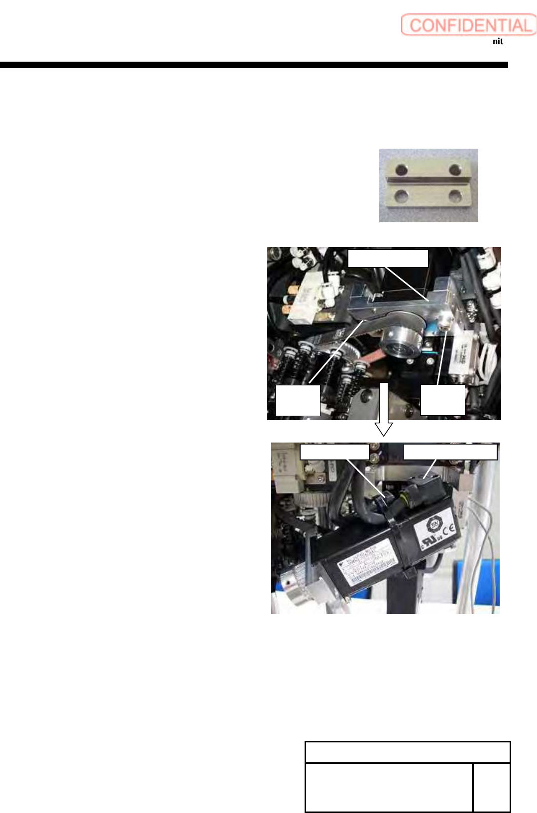
3 Remove the screws (C5x20,C5x15,2-W5) and
Detach the RN Bracket (B).
4 Cut the cable tie locking the wiring of motor.
5 Remove the power cable and the encoder cable
of the motor.
Change Procedure for RN-axis
Motor Unit
RPGB-10501-1
SEET
1/3
RN bracket (B)
C5x15
W5
C5x20
W5
Encoder cable Power cable
Change Procedure for RN Axis Motor Unit
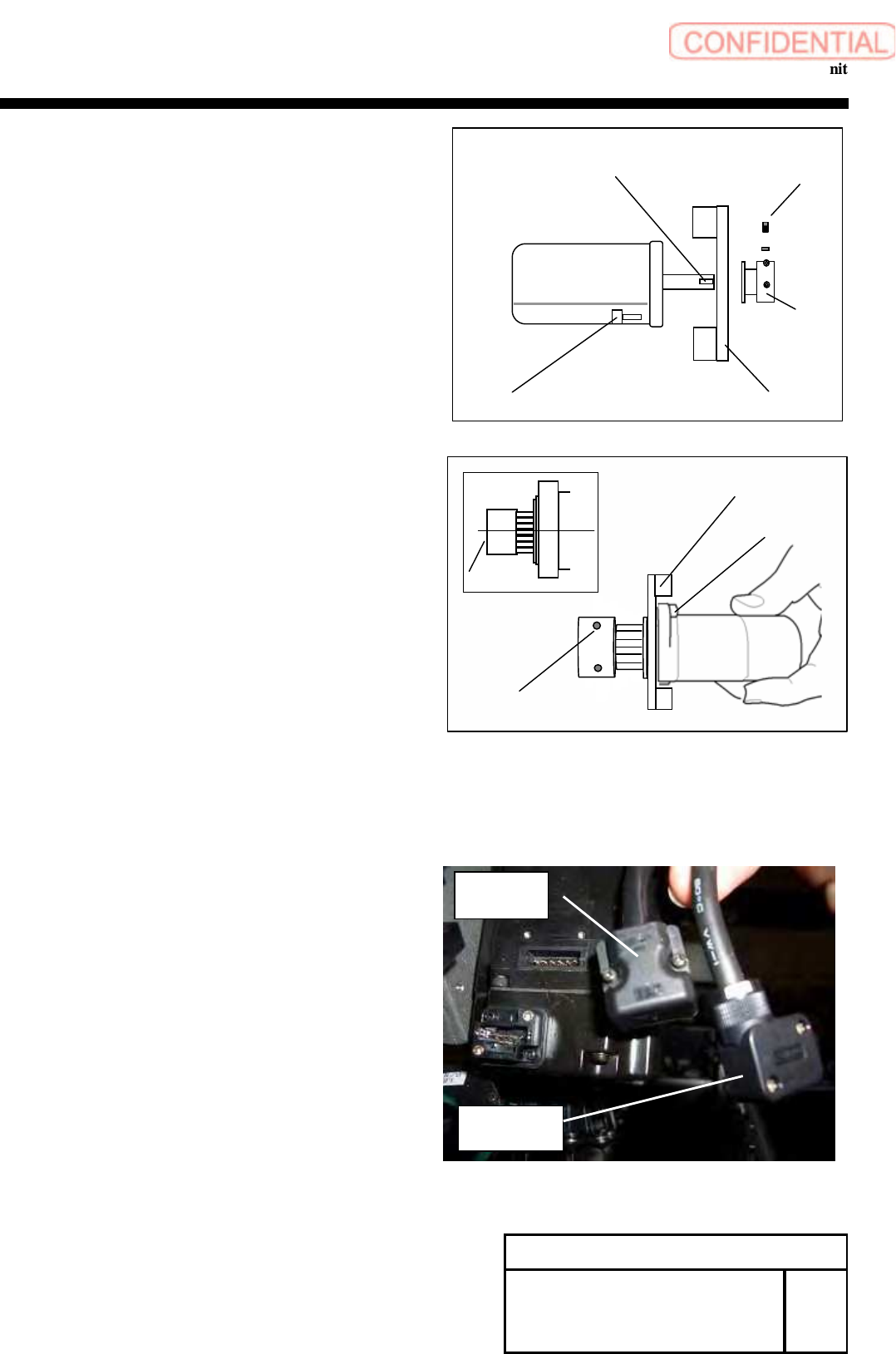
6
Remove the screws (2-H3x8) and the pulley.
CAUTION
There is a set shoe behind the screw which locks the
pulley in the keyless position.
Remove the set shoe, and safe keep it not lose it.
7 Remove the screws (2-C4x10) and RN bracket (B).
[Reassembly]
8 Attach the pulley.
1. Apply adhesive (Locktite 242) to the screws(2-C4x10)
And attach the RN Bracket (B)
2. Inset the key into the spindle of a new motor,
where the key is supplied with the new motor.
CAUTION
When inserting the key, lightly insert it not to
Impose burden on the spindle of the motor.
3. Attach the pulley on the spindle of the new motor.
4. Put the set shoe deep into the hole of screws,
which is to lock the pulley in the keyless position.
5. Apply adhesive (Locktite 242) to the screws (2-H3x8).
6. Align the motor shaft end with the pulley end
Fasten the screws 3-H3x8 to lock the pulley.
9 Connect the power cable and the encoder cable
to the motor.
H3×8
Set Shoe
Align
RN Bracket (B)
C4x10
Change Procedure for RN-axis
Motor
Unit
RPGB-10501-1
SEET
2/3
RN Bracket (B)
Pulley
C4x10
H3
x
8
Set Shoe
Key
Encoder
cable
Power
cable