MAN00000772_SI-G200BB_SVCPDFA.pdf - 第240页
Calibration HLGB-10310-01 Fixed Camera Rcg Height C alibration SHEET 1/5 Fixed Camera Rcg Height Calibration [Necessary jigs] A Length reference nozzle jig B Fixed camera jig base C Thickness gauge (t=0.03 mm) [Procedure…
Calibration
HLGB-10309-01
Calibration Data Edit
SHEET
4/4
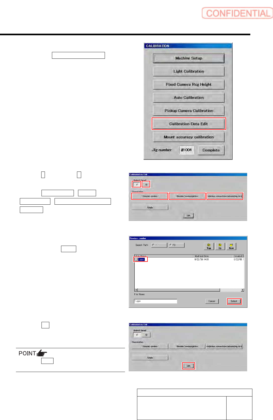
4 Display a Calibration Data Edit screen.
1. Click the Calibration Data Edit button
on the CALIBRATION screen.
Calibration Data Edit screen is displayed.
5 Click the F button or the R button to select a
head to be corrected.
6 Click the Revise center / Revise
Transcription / Transcription correction
according button to select working which
you attempt to correct.
Correction file select screen is displayed.
7 Select a correction file included in the floppy
disk and click the Select button.
Correction file is selected, and the file select screen
closes.
The right screen is an example of file select screen for
rotation center correction.
8 Click the OK button.
The offset value is saved, and the calibration edit
screen closes.
Press the Undo button, then you can return to
previous one calibration data.
Calibration
HLGB-10310-01
Fixed Camera Rcg Height Calibration
SHEET
1/5
Fixed Camera Rcg Height Calibration
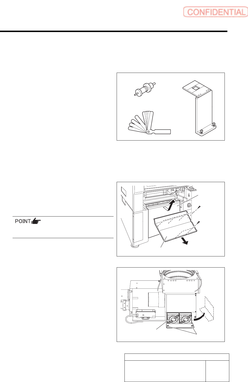
[Necessary jigs]
A Length reference nozzle jig
B Fixed camera jig base
C Thickness gauge (t=0.03 mm)
[Procedure]
1 Press the emergency stop switch to turn off the servo.
2 Turn off the interlock switch and open the door.
3 Remove the lower cover and shooter on
front and rear of the unit.
1. Loosen screw (2-+T4x8) to remove the
lower cover.
Tile the lower cover slightly toward you and pull
the fan cable to remove the lower panel.
2. Loosen screw (2-+T4x8) to remove the
shooter.
4 Loosen cap screws (2-CP5x10) fixing the
fixed camera cooling fan to remove the fan.
Temporarily place the removed fan on the side of the
fixed camera.
A
B
C
Cap screw
Cooling fan
Lower cover
Shooter
Calibration
HLGB-10310-01
Fixed Camera Rcg Height Calibration
SHEET
2/5
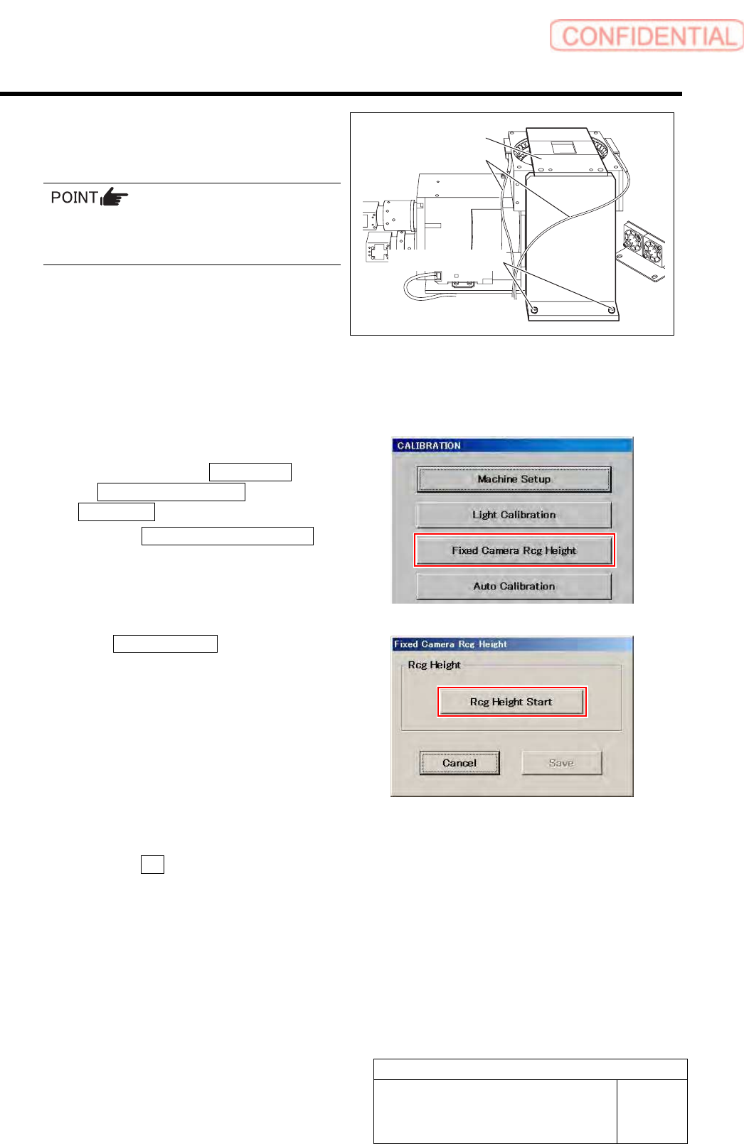
5 Secure the fixed camera jig base with cap
screws (2-CP5x20).
Carry out working with care not to damage the
fiber cable for parts presence/absence detecting
sensor.
6 Turn the emergency stop switch in the arrow direction to release the emergency stop state.
7 Press the [ORG] button on the operation panel to start the origin position return.
When the origin position return is completed, the [ORG] button goes off.
8 Display a Fixed Camera Rcg Height screen.
1. Click in an order of M/C SETUP menu
M/C MAINTENANCE tab
Calibration button.
2. Click the Fixed Camera Rcg Height
button on the CALIBRATION screen.
Fixed Camera Rcg Height screen is displayed.
9 Click the Rcg Height Start button.
“Install nozzle?” is displayed on the message screen.
10 Install the length reference nozzle jig.
1. Click the Yes button.
“Press [START] to move to nozzle installing
position” is displayed on the message screen.
Fixed camera jig base
Fiber cable
Cap screw