MAN00000772_SI-G200BB_SVCPDFA.pdf - 第196页
Set-up HLGB-10207-01 RN A xis Origin Offset Setup SHEET 4/4 3. Input the value (example: 1 10.1) obtained in the pr evious procedur e into the RN Offset b ox, and click the Set button. RN offset value is set.
Set-up
HLGB-10207-01
RN Axis Origin Offset Setup
SHEET
3/4
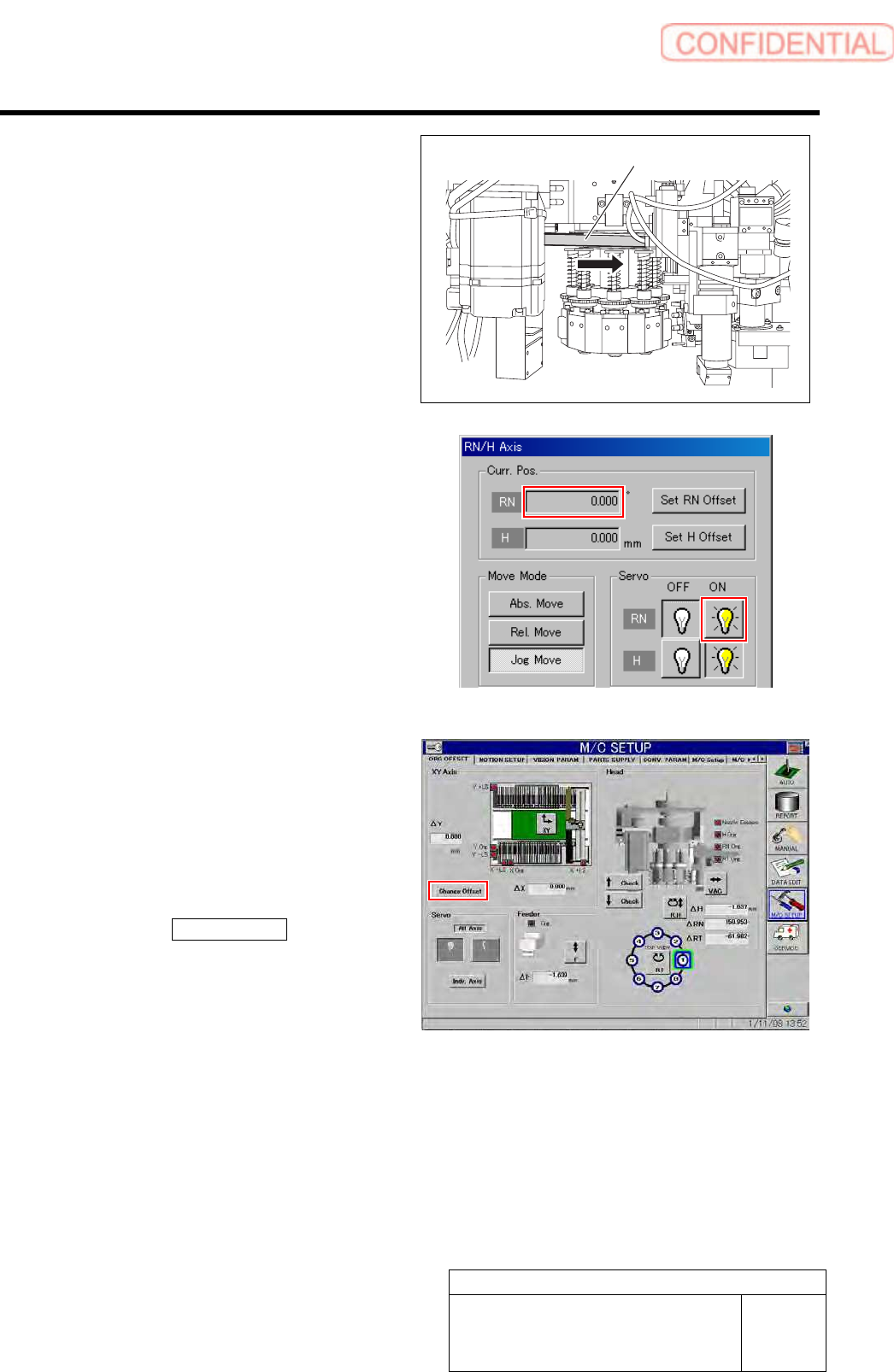
5 Check the rotating angle when rotating the
RN axis belt counterclockwise.
1. Turn on the servo for the RN axis at a
position where the RN axis is rotated
counterclockwise and stops.
2. Take note of angle of the RN axis
displayed on the RN/H Axis screen.
(Example: -149.5˚)
6 Set a half of the value for which the angle
when rotated clockwise and the angle when
rotated counterclockwise are added as a RN
axis offset value.
1. Calculate the offset value of the RN axis.
Example: (369.7 + (-149.5)) / 2 = 110.1
2. Click the Change Offset button on the
ORG OFFSET screen.
Offset screen is displayed.
RN axis belt
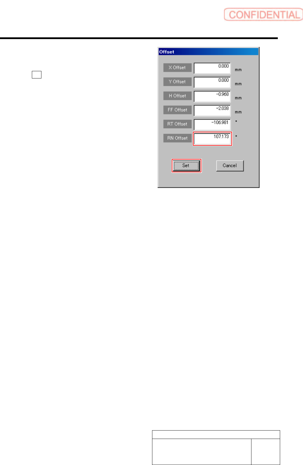
Set-up
HLGB-10207-01
RN Axis Origin Offset Setup
SHEET
4/4
3. Input the value (example: 110.1)
obtained in the previous procedure
into the RN Offset box, and click the
Set button.
RN offset value is set.
Set-up
HLGB-10208-01
Pickup Check Camera Setup
SHEET
1/5
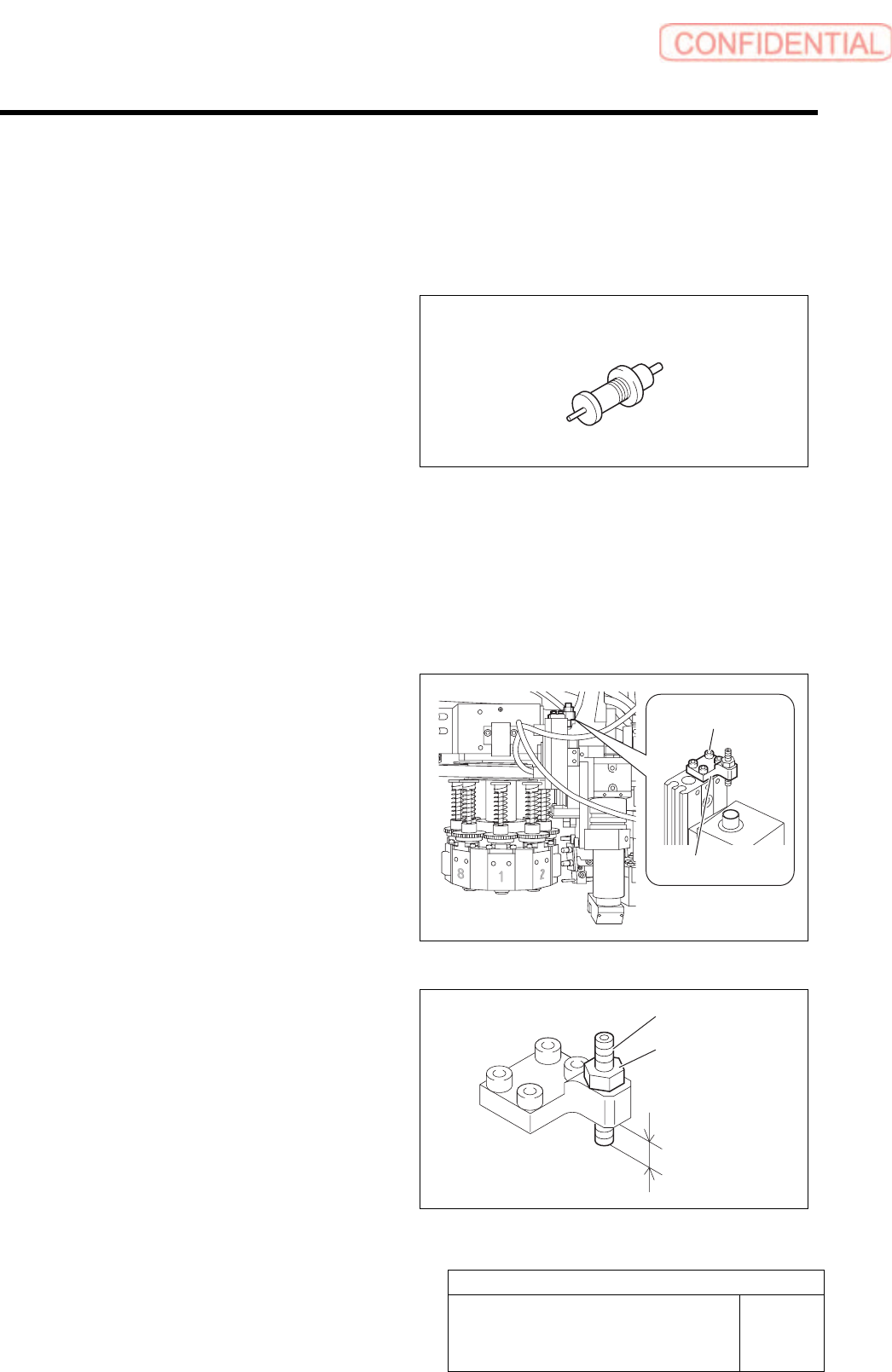
Pickup Check Camera Setup
Perform this working on both heads on the front side and rear side.
[Necessary jigs]
• Length reference nozzle jig
• Scale (about 150 mm)
[Position adjustment for rise end stopper]
1 Move the head to a position where working can be easily performed and turn on the power.
2 Remove the head from the F axis unit.
For removal procedure of F axis unit, refer to the “F axis belt replacing procedure [RPGB-10201-01]”.
3 Loosen cap screws (4-CP2.5x6) to remove
the stopper bracket.
4 Adjust protrusion amount of the stopper to
4.0mm.
1. Loosen the locknut.
2. Adjust protrusion amount of the
stopper to 4.0mm.
3. Tighten the locknut.
Length reference nozzle jig
Stopper bracket
Cap screw
Stopper
Locknut
4.0 mm