MAN00000772_SI-G200BB_SVCPDFA.pdf - 第247页
Calibration HLGB-1031 1-01 Pickup Position Setup SHEET 3/9 2. Check jig information ( Δ Y) attached on the side of the pickup p oint jig. 3. Enter value of Δ Y written on the sid e of the pickup point jig into the Δ Y bo…
Calibration
HLGB-10311-01
Pickup Position Setup
SHEET
2/9
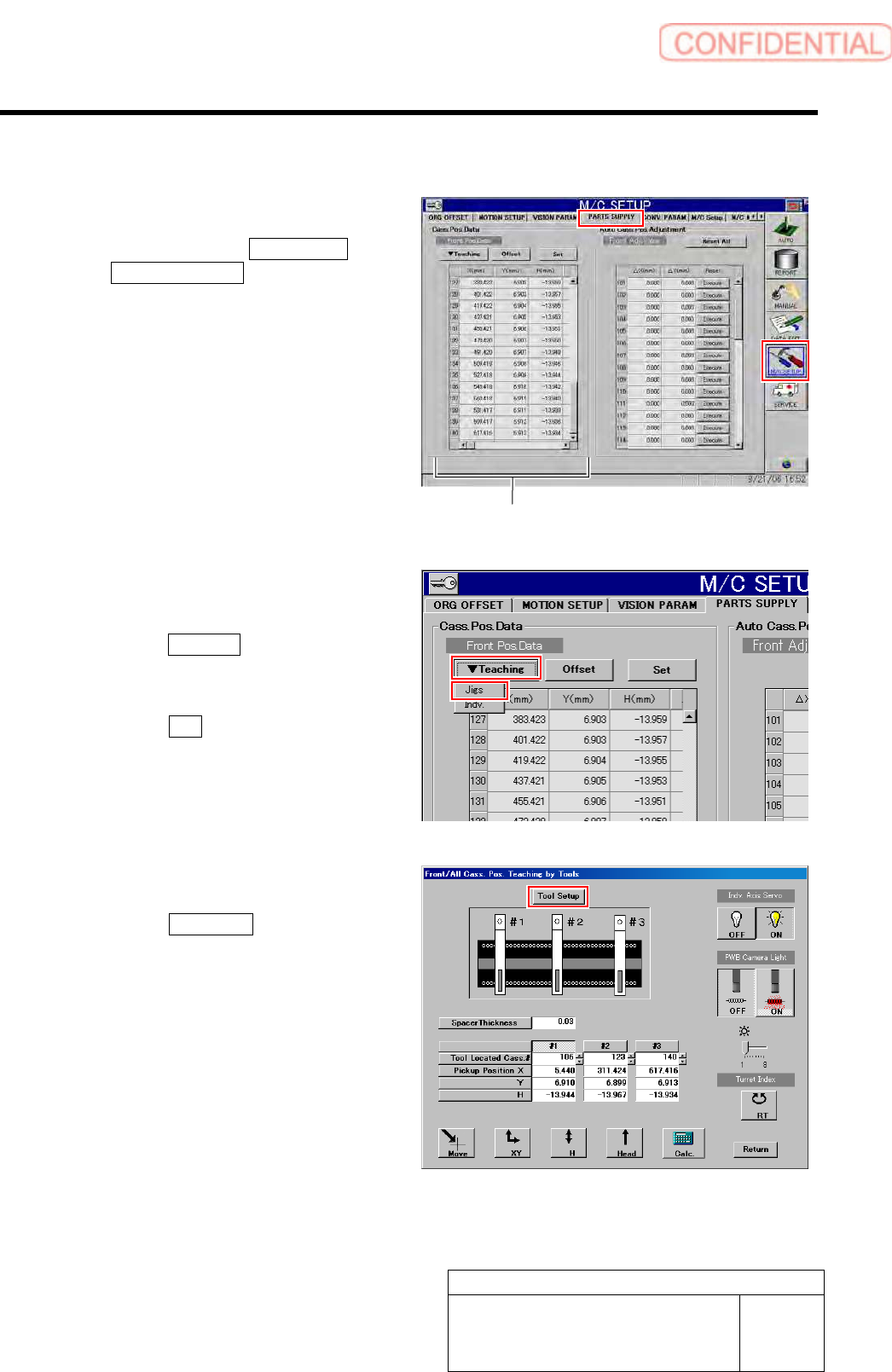
2 Press the [ORG] button on the operation panel to perform origin position return.
3 Display a PARTS SUPPLY screen.
1. Click in an order of M/C SETUP menu
PARTS SUPPLY tab.
Cassette position coordinates are displayed on
left part of the PARTS SUPPLY screen.
4 Display a Front/All Cass. Pos. Teaching by
Tools screen.
1. Click the Teaching button on the Front
Pos. Data to display a drop down
menu.
2. Click the Jigs in the drop down menu.
The Front/All Cass. Pos. Teaching by Tools
screen is displayed.
5 Set the jig.
1. Click the Tool Setup button.
Tool Setup screen is displayed.
Cassette position coordinates
Calibration
HLGB-10311-01
Pickup Position Setup
SHEET
3/9
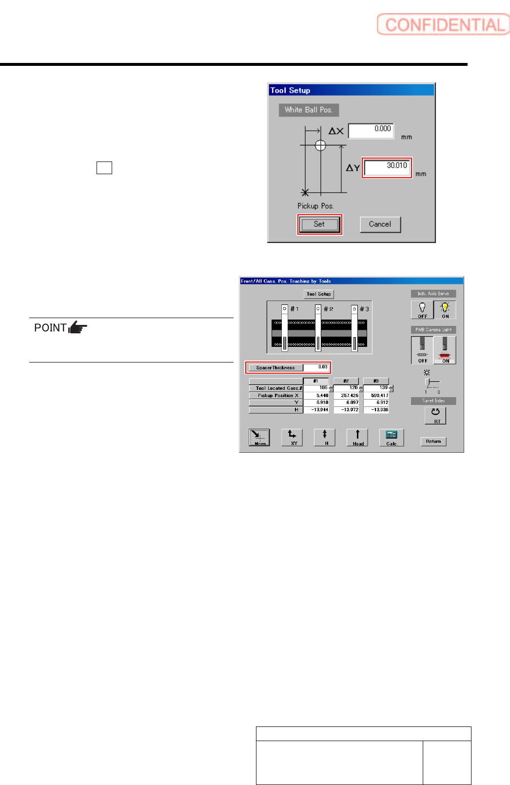
2. Check jig information (ΔY) attached
on the side of the pickup point jig.
3. Enter value ofΔY written on the side
of the pickup point jig into the ΔY box
on the jig setting screen.
4. Click the Set button.
The value of ΔY is set and the jig setting screen
is closed.
5. Input thickness of “0.03” of thickness
gauge used for H axis position data
teaching.
The value of the spacer thickness becomes
offset value when acquiring H coordinate.
Calibration
HLGB-10311-01
Pickup Position Setup
SHEET
4/9
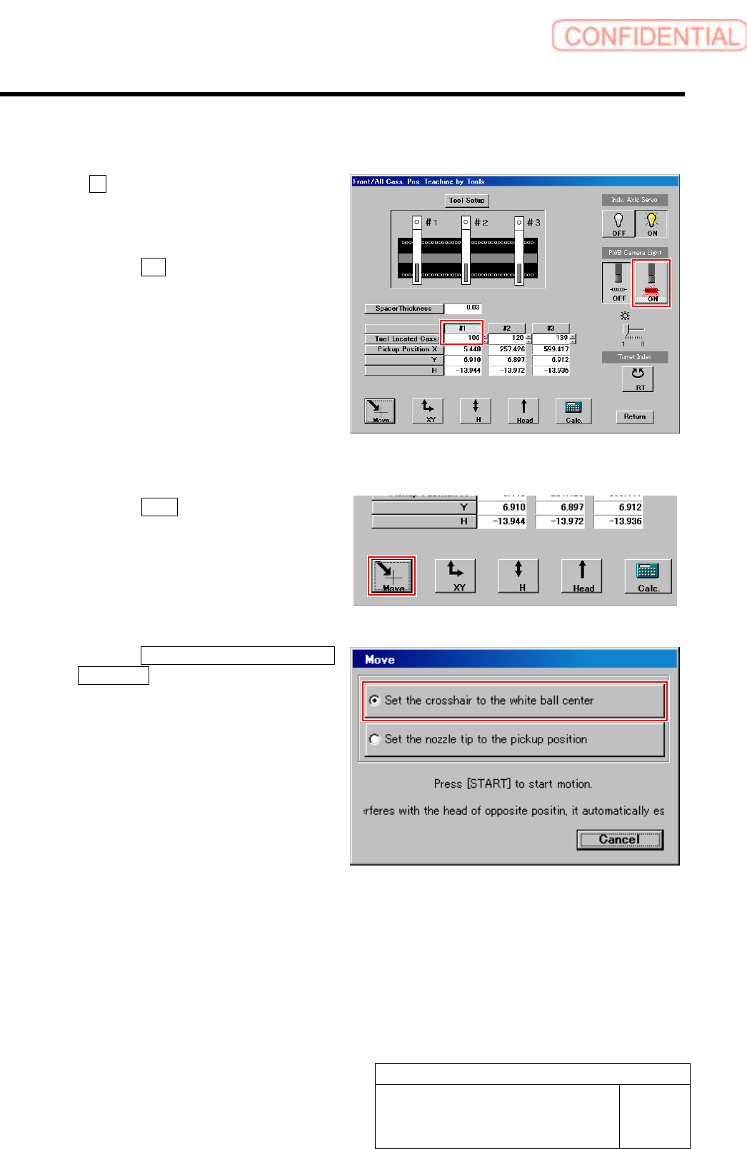
[XY Position Data Teaching]
1 Click #1 and input “106” in the input box for
Tool Located Cass.
2 Light up the PWB camera light.
1. Click the ON button on the PWB
camera light.
The PWB camera light lights up.
2. Set brightness of the PWB camera
light to “6” or “7”.
3 Move the PWB camera to the pickup point.
1. Click the Move button.
Move screen is displayed.
2. Click the Set the crosshair to the white
ball center button.
3. Press the [START] button on the
operation panel.
The PWB camera automatically moves to nearly
the center of the pickup point.
Hole on the pickup point jig is displayed on the
PARTS DISPLAY window at this time.