MAN00000772_SI-G200BB_SVCPDFA.pdf - 第628页
4. Basic Operations of the Multifunctional Mounter TFGB-10101-0 1 SI-G200 (B Head) Overview SHEET 13/20 <Points to Note> - When parts in the norm al mode and ones in the high-Accuracy m ode coexist in one pat h dur…
4. Basic Operations of the Multifunctional Mounter
TFGB-10101-01
SI-G200 (B Head) Overview
SHEET
12/20
4-5 Mounting
The H axis descends above the mounting position, and picked up parts are mounted onto a PWB.
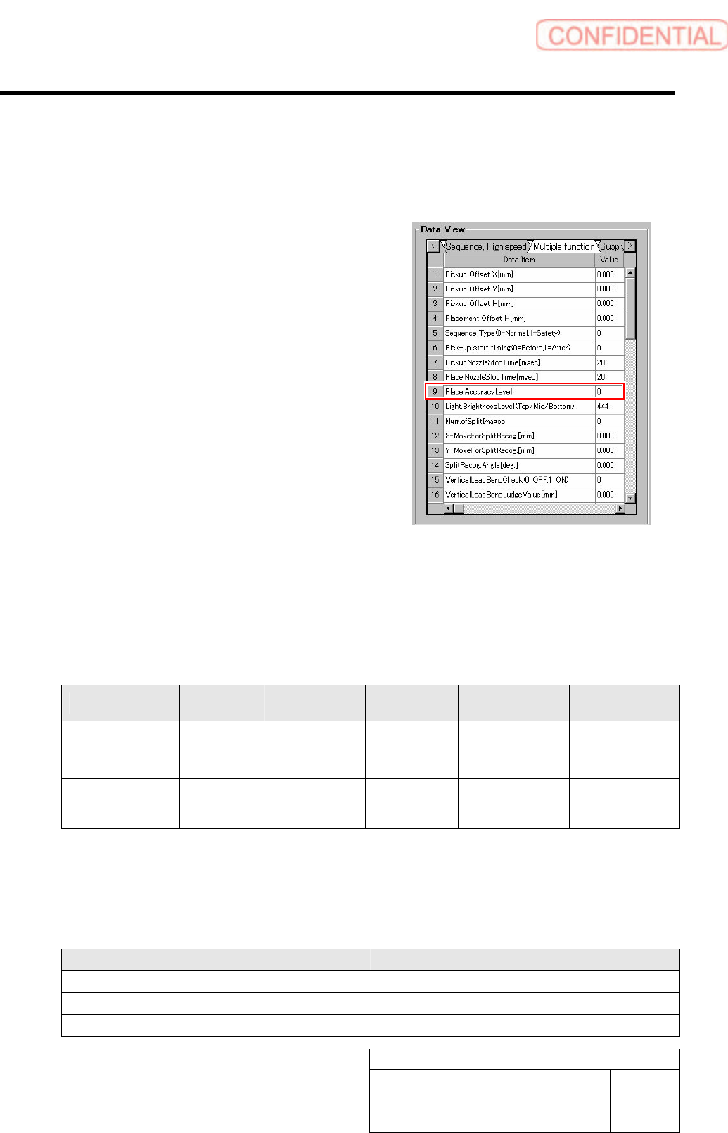
[Accuracy level]
There are two types for the Accuracy level: normal
mode and high-Accuracy mode. For parts that need
higher positioning Accuracy when they are mounted,
the high-Accuracy mode is selected. The Accuracy
level is defined in part data, and it can be set in
“Sequence (Multifunction)” displayed after “Data
Editing” and “Part Management” have been selected in
this order.
Depending on the setting for the Accuracy level, the recognition angle, recognition method, and mounting
operation differ. In the normal mode, parts are recognized with the recognition angle being 0 degree, and
they are mounted continuously. In the high-Accuracy mode, in order to improve the mounting Accuracy,
each of the parts is recognized with an angle suitable for mounting it and then mounted.
Difference in Pickup, Antibacklash, Recognition Angle, Recognition Method, and Mounting
Operation, Depending on the Accuracy Level
Accuracy Level Pickup Antibacklash
Recognition
Angle
Recognition
Method
Mounting
Operation
Disable 0 degree
Global/Individual
Split
0
(normal mode)
Continuous
pickup
Enable 0 degree Individual/split
Continuous
mounting
1
(high-Accuracy mode)
Continuous
pickup
Enable Mounting angle Individual/split
Each of parts is
recognized and
mounted.
When parts whose Accuracy level is the normal mode fall under one of the items below, an antibacklash
operation is performed forcibly for them. The anti-backlash motion for the global recognition parts is not
executed.
Antibacklash Operating Conditions for Parts in the Normal Mode
Item Condition
Part thickness 3.00 mm or more
Maximum number of leads (in one direction) One or more
Total number of balls (BGA/odd-shaped parts (with balls)) Four balls or more
4. Basic Operations of the Multifunctional Mounter
TFGB-10101-01
SI-G200 (B Head) Overview
SHEET
13/20
<Points to Note>
- When parts in the normal mode and ones in the high-Accuracy mode coexist in one path during part
pickup, parts with the same Accuracy level as that of the first parts to be picked up are picked up first
and then mounted. The remaining parts are passed on to a recovery path. In addition, when machine
model data is downloaded, a warning message appears.
Pickup and Mounting Operation When Parts in One Mode
and Ones in the Other Coexist in One Path
Accuracy Level of the First Parts to Be
Picked Up
Pickup and Mounting Operation
Normal mode
Only parts in the normal mode (including globally recognized parts) are picked up.
(The remaining parts are passed on to a recovery path.)
High-Accuracy mode
Only parts in the high-Accuracy mode are picked up.
(The remaining parts are passed on to a recovery path.)
In these cases, DAS needs to be operated so that parts in one mode and ones in the other do not coexist in
one path.
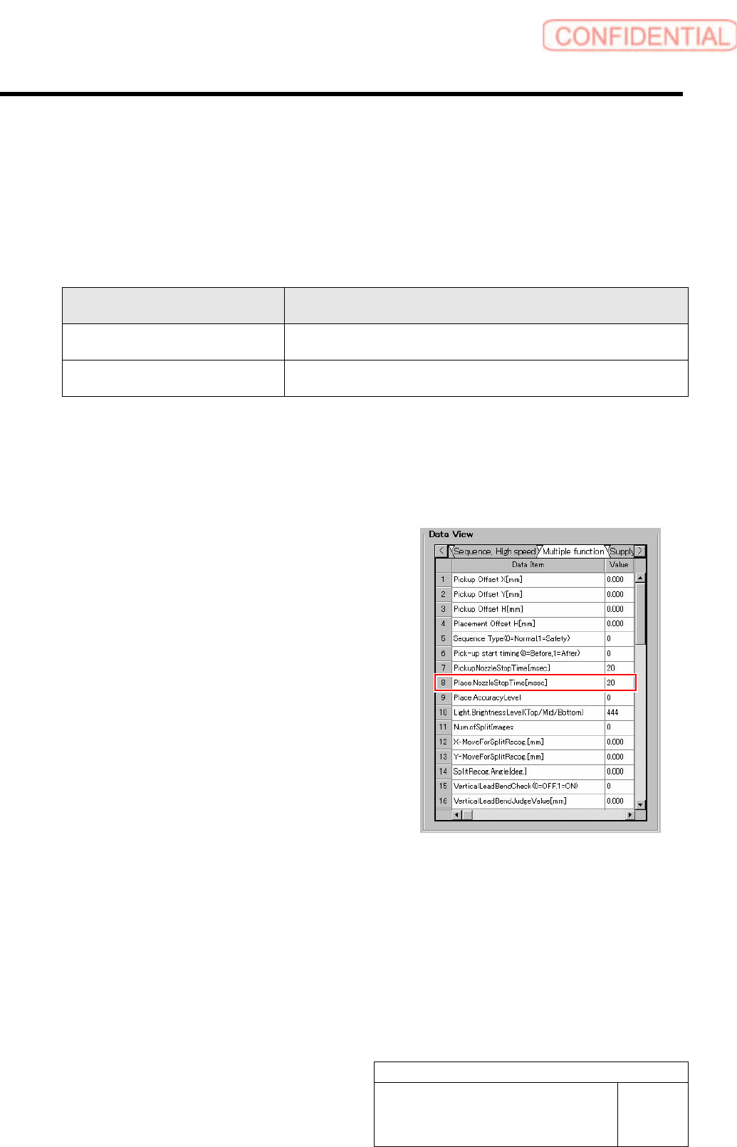
[Place Nozzle Stop Time]
Because the multifunctional mounter handles larger-size
parts that the high-speed one cannot, the stationary time of
the former is as follows:
When override is 60% or less:
Values input in part data are used.
When override is 61% or more:
-10 x (overall override: 1.0 to 0.01) + 13 msec
* Override means H axis override x overall override.
4. Basic Operations of the Multifunctional Mounter
TFGB-10101-01
SI-G200 (B Head) Overview
SHEET
14/20
4-6 Nozzle Changer
The multifunctional mounter has employed the 24-nozzle gradual replacement method in which nozzles
are replaced automatically during automatic production.
Because nozzles are controlled inside the mounter, nozzles attached to the head cannot be used until nozzle
ID recognition is conducted. Nozzles used for production need to be mounted correctly on the nozzle
changer when the machine model is switched. When nozzles are attached to the head manually, nozzles
attached in the wrong direction cannot be housed in the nozzle changer, which may damage the nozzles
and the head.
- Nozzle replacement during automatic production
The multifunctional head takes out necessary nozzles from the nozzle changer according to the situation
and performs operations for production.
While one head is replacing nozzles, the other is in a standby state. Therefore, as the number of times
nozzles are replaced is larger, takt time will be longer.
It is recommended that production data be created so that the number of times nozzles are replaced is as
small as possible. DAS arranges data so that the number of times nozzles are replaced is as small as
possible.
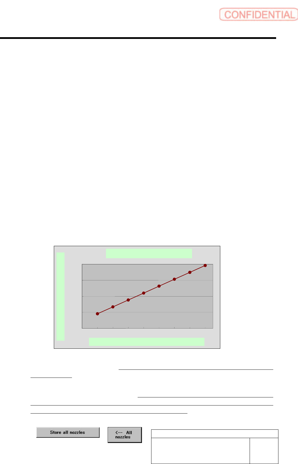
- Time it takes for one nozzle to be replaced (reference)
Standard nozzle replacement time is shown in the graph below. It takes about 4.5 seconds for the first
nozzle to be replaced, and, after that, it takes about 2.1 seconds for one nozzle to be replaced.
Time It Takes for One Nozzle to Be Replaced
<Points to Note>
- When setting up the nozzle changer, never fail to check the result of the setup by using the individual
teaching function.
- After nozzles have been housed, when it is judged by the pickup check camera that the inner shaft has
not returned completely, the alarm is raised. When the XY-axis operation is performed with this state
maintained, the inner shaft may contact the nozzle changer and be damaged. Therefore, visually check to
what extent the inner shaft has returned, and then return it manually.
- Before installing the software, be sure to house all nozzles by using the buttons below.
Standard nozzle replacement time
0
500
1000
1500
2000
012345678
Number of nozzles to be replaced N (N housed, N mounted)
Time it takes for nozzles to be replaced (msec)