MAN00000772_SI-G200BB_SVCPDFA.pdf - 第644页
F axis movable part RPGB-10101-01 F A xis Belt Replacement Proced ure SHEET 5/9 [Inst allment] 1 Fasten 2-C3x8 screws to fix the belt by the joint. Clamping torque : 98cN.m Lock T ight 242 is applied to the scre w . 2 Fa…
F axis movable part
RPGB-10101-01
F Axis Belt Replacement Procedure
SHEET
4/9
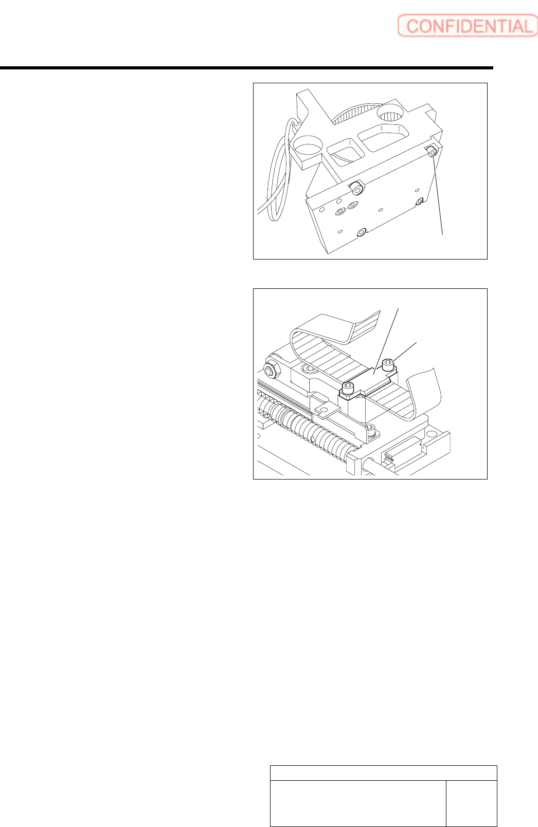
12 Unscrew 4-C4x10 screws to remove the
parts feeder assembly from the main frame.
13 Unscrew 2-C3x8 screws to loosen the joint
to remove the belt.
4-C4x10
2-C3x8
Joint
F axis movable part
RPGB-10101-01
F Axis Belt Replacement Procedure
SHEET
5/9
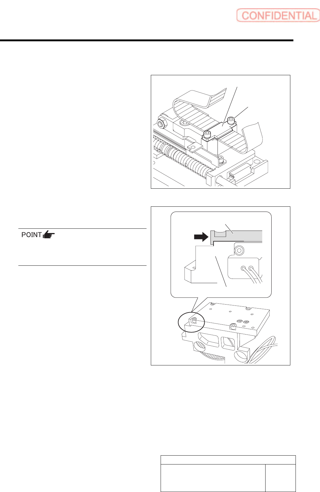
[Installment]
1 Fasten 2-C3x8 screws to fix the belt by the
joint.
Clamping torque : 98cN.m
Lock Tight 242 is applied to the screw.
2 Fasten 4-C4x10 screws and install the parts
feed assembly to the main frame.
Press the parts feed assembly against the main
frame assembly.
Clamping torque : 196cN.m
2-C3x8
Joint
Parts feed assembly
Main frame
F axis movable part
RPGB-10101-01
F Axis Belt Replacement Procedure
SHEET
6/9
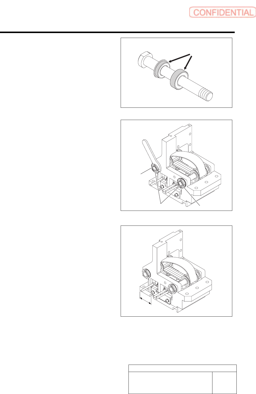
3 Install two pulley shafts to the main frame
assembly.
Apply Lock Tight 242 to the eight locations on the
outer circumfelence of the Lock Tight 242.
4 Fasten the U nut to fix the pulley shaft.
5 When the sensor bracket has been
removed, install the sensor bracket 26.5 mm
away from the frame end as shown in the
figure.
Lock Tight
Pulley shaft
U nut
U nut
26.5mm