MAN00000772_SI-G200BB_SVCPDFA.pdf - 第662页
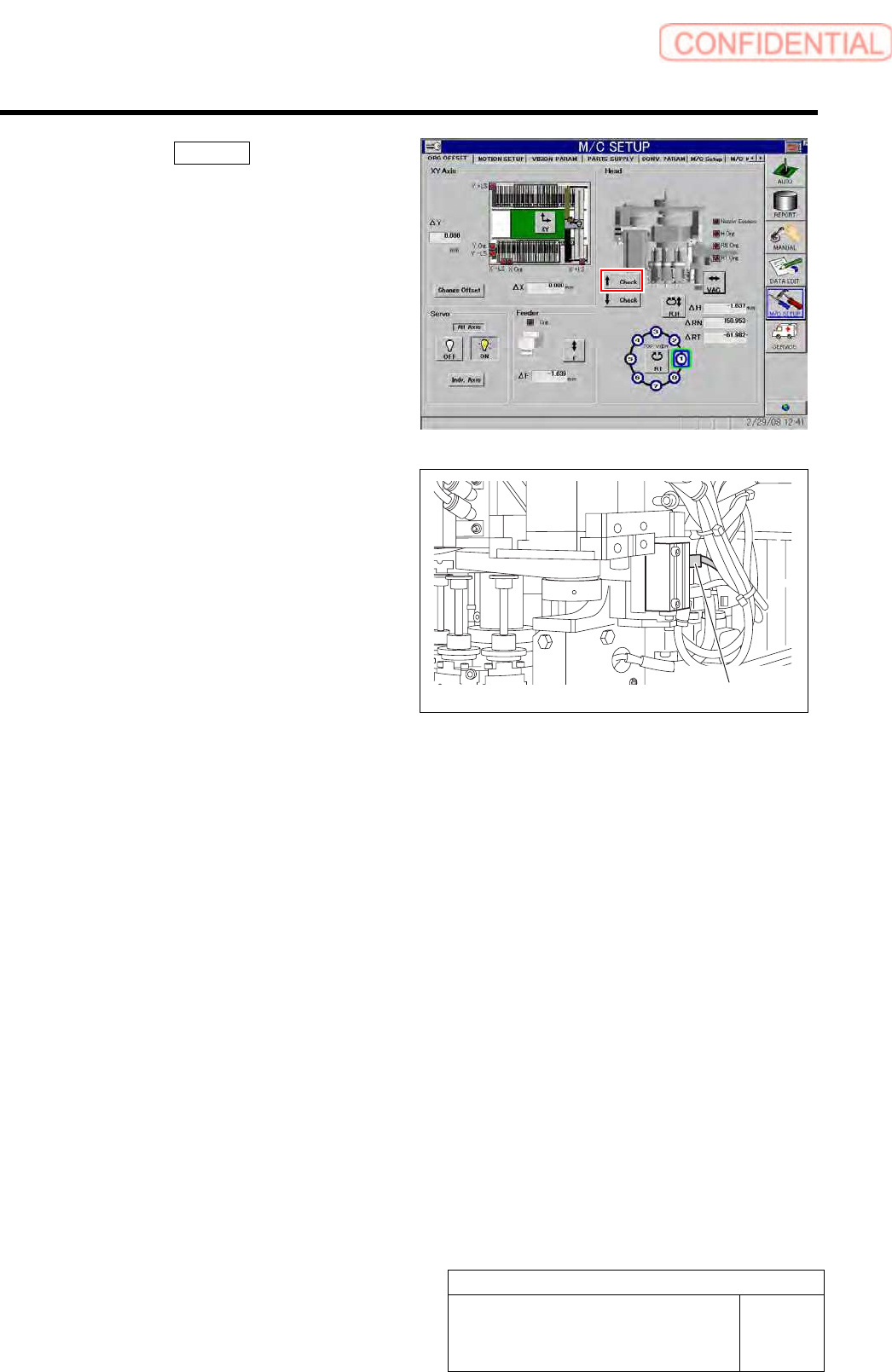
Pickup Check Camera Part RPGB-10202-01 Pickup Check Light Up/Do wn Cylinder Replacement SHEET 7/7 4. Click the ↑ Check button to check a position of the risin g end of the light unit. 5. Adjust the position of the upper …
Pickup Check Camera Part
RPGB-10202-01
Pickup Check Light Up/Down
Cylinder Replacement
SHEET
6/7
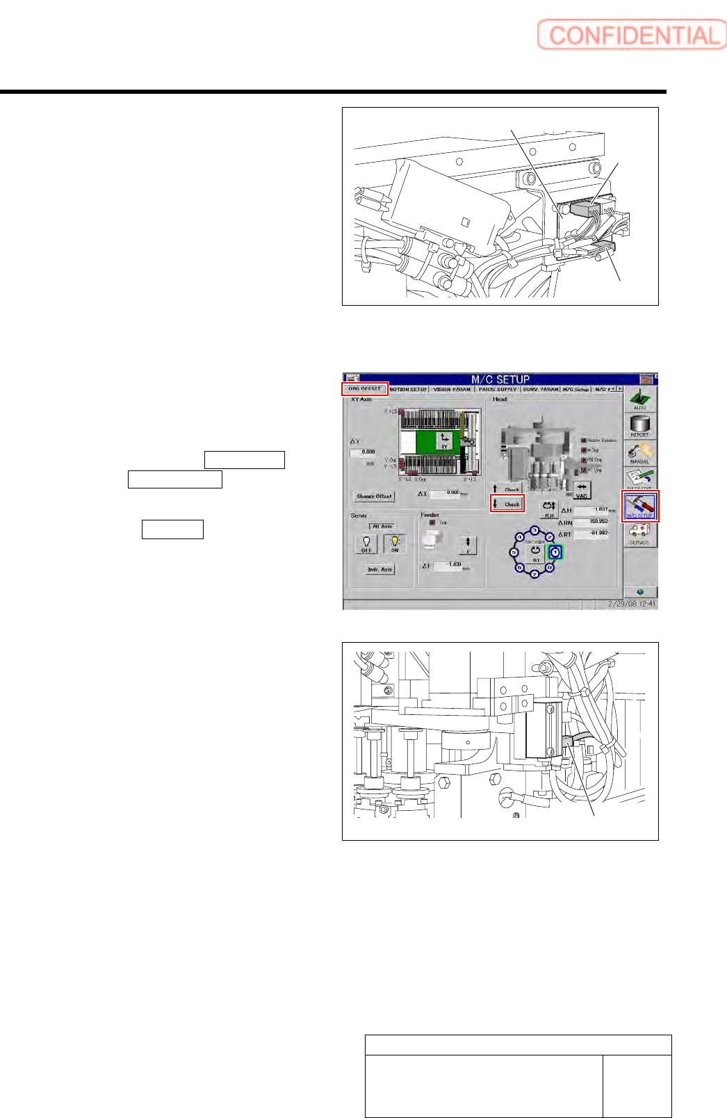
8 Connect the SSB-3 and SSB-5 connectors
to the SSB board.
9 Bundle the cable and air tube together using
the cable tie (Insulock).
10 Connect the air supply and power on.
11 Adjust and check the position of the cylinder
up/down sensor using the buttons on the
ORG offset screen of M/C SETUP.
1. Click in an order of M/C SETUP
menuORG OFFSET tab.
The origin offset careen is displayed.
2. Click the ↓ Check button to check a
position of the lowering end of the
light unit.
3. Adjust the position of the lower
cylinder sensor and adjust the position
of the lowering end of the light unit.
SSB board
SSB-3
SSB-5
Cylinder sensor
Pickup Check Camera Part
RPGB-10202-01
Pickup Check Light Up/Down
Cylinder Replacement
SHEET
7/7
4. Click the ↑ Check button to check a
position of the rising end of the light
unit.
5. Adjust the position of the upper
cylinder sensor and adjust the position
of the rising end of the light unit.
Cylinder sensor
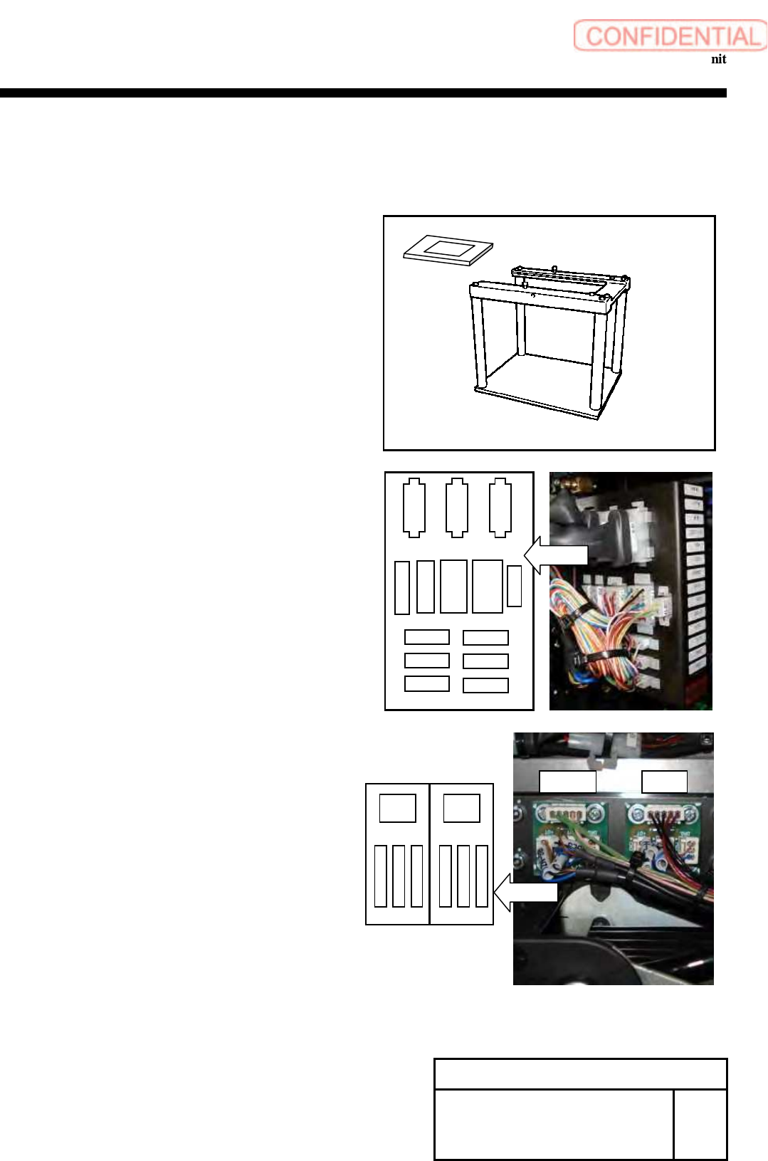
Change Procedure for Head Unit
Change procedure for Head Unit
[Necessary jigs]
Head block
Assembly plate(G200 original)
[Disassembly]
1 Expand conveyor width to the maximum.
2 Turn off a power supply and close an air main
cock.
3 Open the front and rear side doors of the main
body.
4 Push the X-axis frame to the center and the head base
to an easy-to-work position.
5 Remove all nozzles.
6
Remove all the following connectors ,
and cut the cable tie locking the wiring.
1. PWB camera (CAME1)
2. Connector plate
(HM,RTM,RNM,CSFT,FSEN2,LED,PD,CSFT-LS,HE,
RTE,RNE,VAC-2,RTS,RNS)
3. Pick up Camera(CAME2)
4. HLSB and PD-LSB
(BS-NZL,PDLS-3,PDLS-4,HLS-2,HLS-3,HLS-4)
5. Encoder (DE1)
Change Procedure for Head
Unit
RPGB-10301-1
SEET
1/4
CSFT
FSEN2
LED
PD
CSFT-LS
HM
RTM
RNM
HE VAC-2
RTS
RNE
RTE
Layout
RNS
HLSB
PD-LSB
Layout
BS
-
NZL
PDLS
-
3
PDLS
-
4
HLS
-
2
HLS
-
3
HLS
-
4