MAN00000772_SI-G200BB_SVCPDFA.pdf - 第183页
Set-up HLGB-10204-01 PWB Camera Setup SHEET 3/4 Jog-move the head part until the lev el dif ference part is displayed on the PCBOARD DISPLA Y screen. * A section displayed in white on the PCBOARD DISPLA Y screen is trans…
Set-up
HLGB-10204-01
PWB Camera Setup
SHEET
2/4
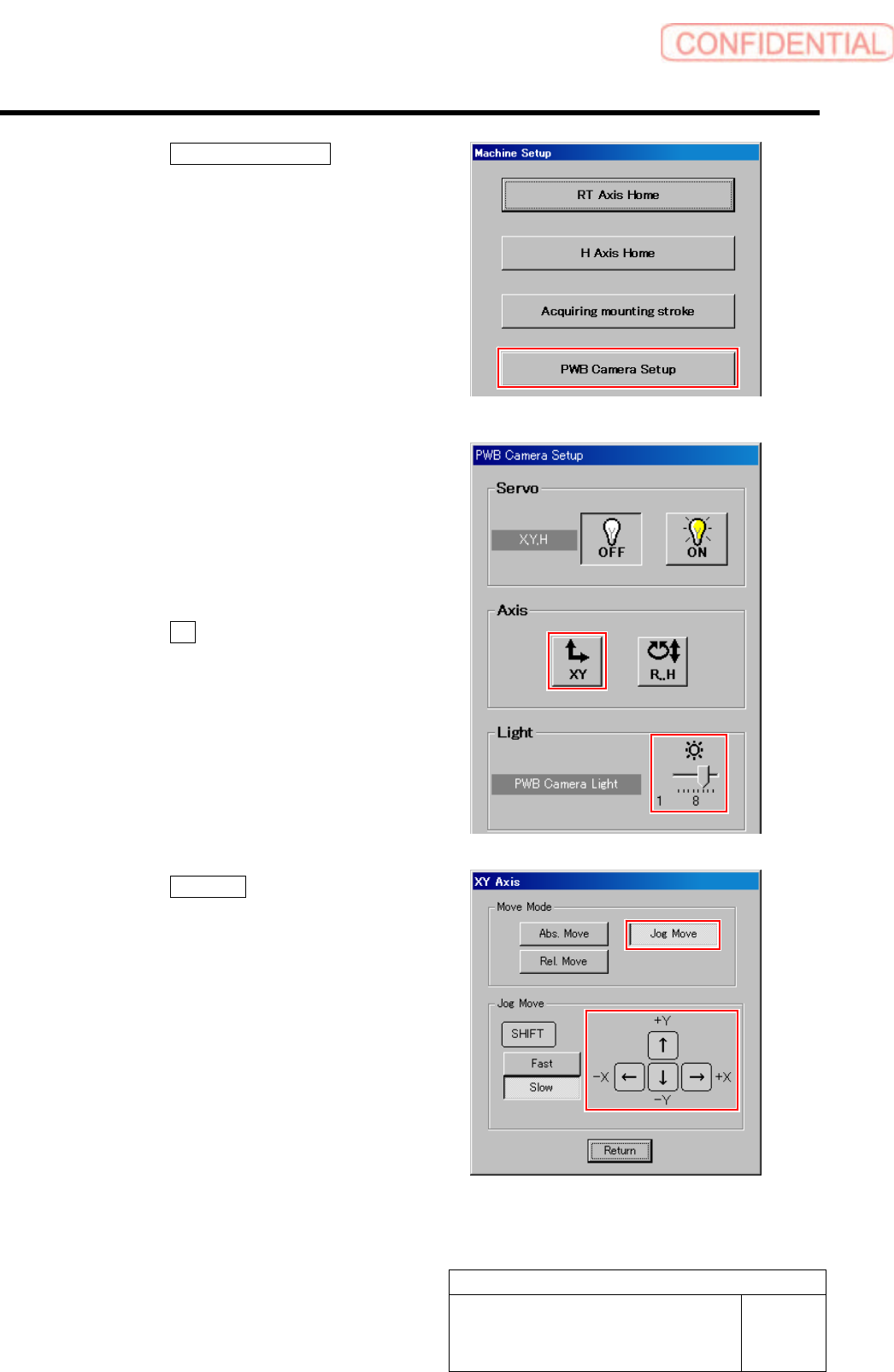
4. Click the PWB Camera Setup button
on the Machine Setup screen.
PWB Camera Setup screen is displayed.
3 Set brightness of the PWB camera light to
“6” or “7”.
4 Move the head to a position where the
transfer rail is displayed on the PCBOARD
DISPLAY screen.
1. Click the XY button on the PWB
Camera Setup screen.
XY Axis screen is displayed.
2. Click the Jog Move button.
3. Press the cursor key to jog-move the
head part onto the transfer rail.
Set-up
HLGB-10204-01
PWB Camera Setup
SHEET
3/4
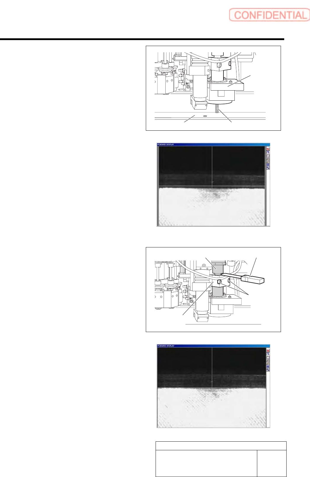
Jog-move the head part until the level difference
part is displayed on the PCBOARD DISPLAY
screen.
* A section displayed in white on the PCBOARD
DISPLAY screen is transfer rail.
5 Adjust position of the PWB camera.
1. Loosen cap screws (2-CP4x8) fixing
the PWB camera.
2. Put thickness gauge of 1.0mm between
the PWB camera and the camera
support bracket and temporarily fix
them.
3. Adjust inclination of the transfer rail
displayed on the PCBOARD DISPLAY
screen so as to align it with the
cross-hair line.
4. After adjusting inclination, tighten the
cap screws (2-CP4x8) to fix the PWB
camera.
5. Remove the thickness gauge.
Transfer rail
Illumination light
PWB camera
Camera Support
bracket
Eyepiece tube
Thickness gauge
CP4x8

Set-up
HLGB-10204-01
PWB Camera Setup
SHEET
4/4
6 Continuously perform auto calibration.
For auto calibration procedure, refer to the “Auto Calibration (Recognition of relationship between PWB coordinate and
mechanism coordinate)” [HLGB-10304-01] and later.