MAN00000772_SI-G200BB_SVCPDFA.pdf - 第295页
Adjustment HLGB-10403-01 H A xis Gear Z-phase Matching SHEET 3/5 6 Re-start the unit. 1. Close the explo rer window . 2. Press the power off switch. Shutting down of the system starts and the power is automatically shut …
Adjustment
HLGB-10403-01
H Axis Gear Z-phase Matching
SHEET
2/5
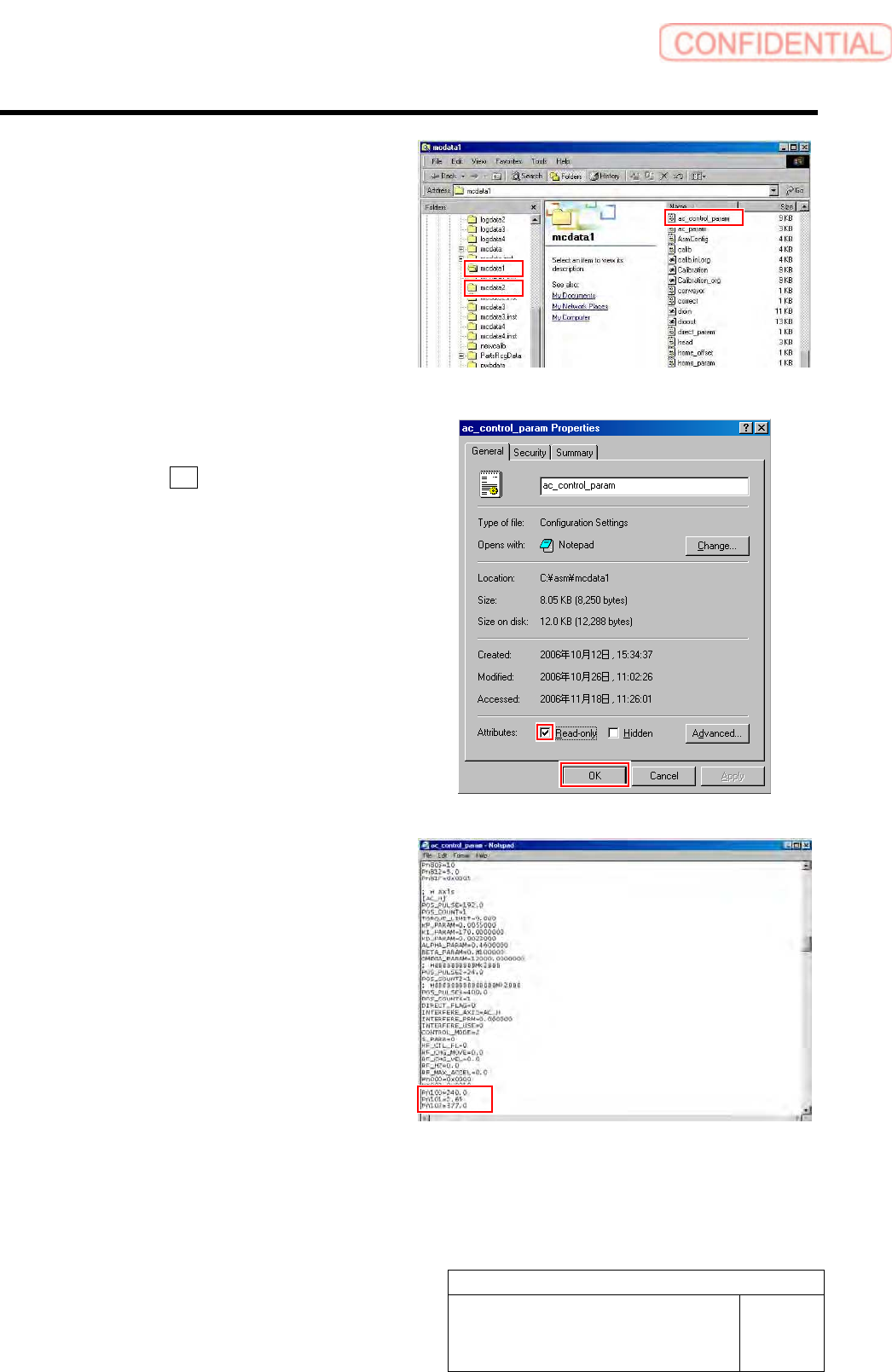
4 Put ac_control_param.ini file for front side
and rear side into a rewritable status.
1. For the front side, open Properties
window for ac_control_param.ini file
in C:¥asm¥mcdata1.
2. For the rear side, open Properties
window for ac_control_param.ini file
in C:¥asm¥mcdata2.
Right-click the file and select “Properties” from
the shortcut menu to open the Properties window.
3. Uncheck “Read-only” on the Properties
window of the ac_param.ini file.
4. Click the OK button.
5 Change the values in the
ac_control_param.ini file for the front side
and rear side.
1. Open the ac_control_param.ini file by
Notepad.
2. Change the value of
PN100-PN101-PN102 of [AC_H].
PN100 (Speed Loop Gain) 180.0 40.0
PN101
(Speed Loop Integral Constant) 3.54 20.0
PN102 (Position Loop Gain) 282.7 40.0
3. Save the ac_control_param.ini file and
end.
4. Open the Properties window of the
ac_control_param.ini file and check
the “Read-only”.
Adjustment
HLGB-10403-01
H Axis Gear Z-phase Matching
SHEET
3/5
6 Re-start the unit.
1. Close the explorer window.
2. Press the power off switch.
Shutting down of the system starts and the power
is automatically shut off.
3. Press the power on switch.
The system starts, and the set value is reflected
on the equipment.
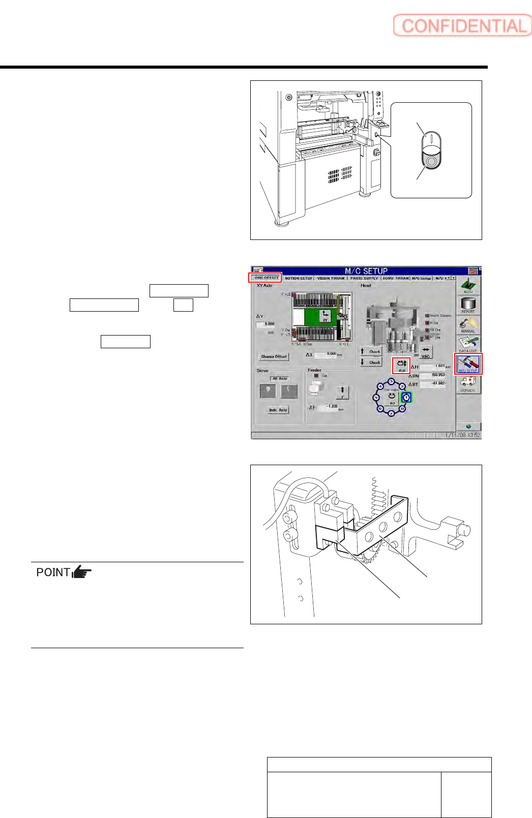
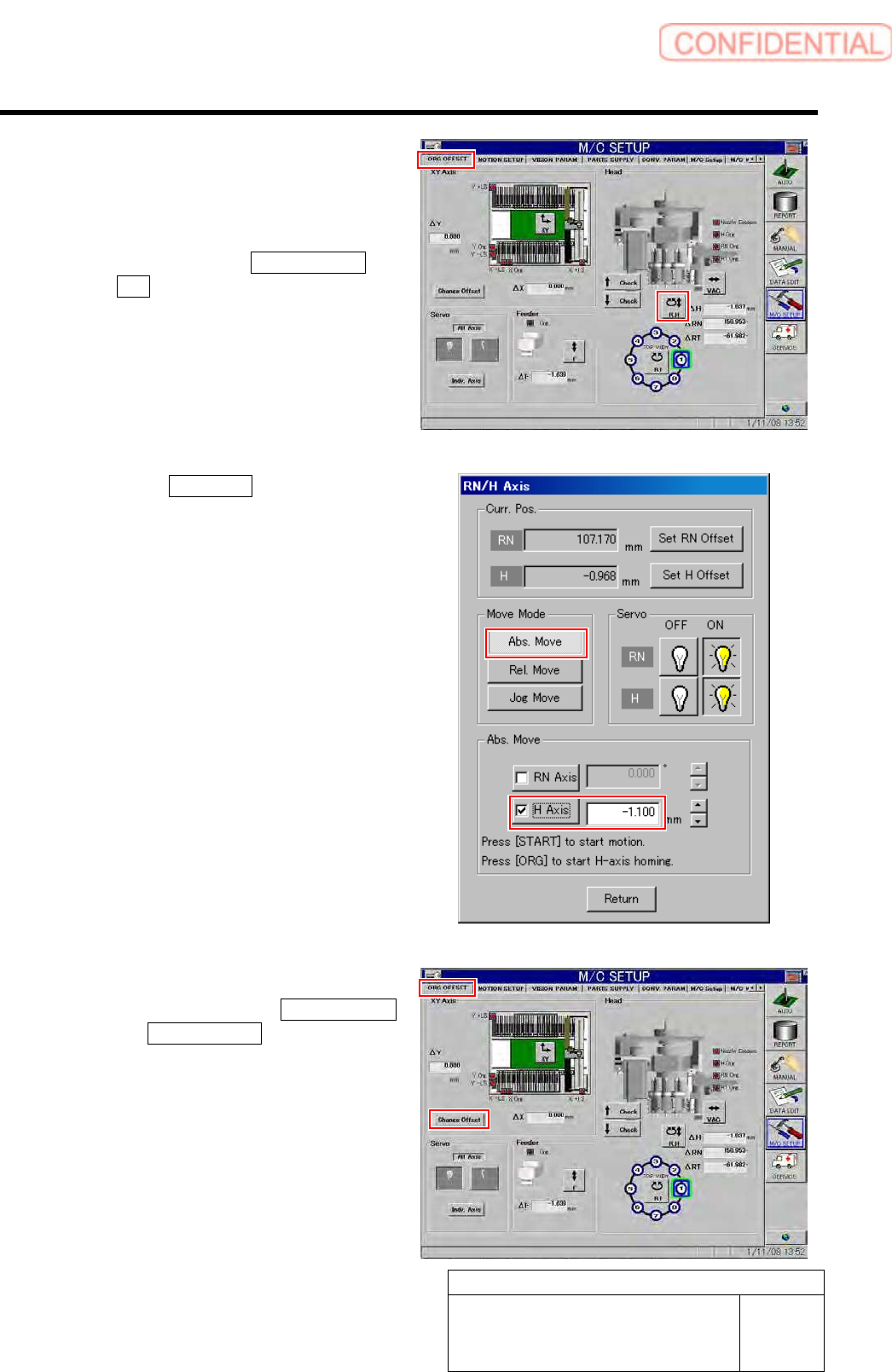
7 Perform origin position return for H axis only.
1. Click in an order of M/C SETUP menu
ORG OFFSET tab R.H button.
RN/H Axis screen is displayed.
2. Click the Abs. Move button for move
mode and put checkmark on H axis.
3. Press the [ORG] button on the
operation panel.
Origin position return is performed for the H axis
only.
8 Check that the motor shaft is idling while
origin position return is performed, once
escape the dog for H axis sensor from the
ORG sensor.
The motor shaft slowly stops in Z-phase after a few
seconds.
Unless the gear is free against the motor shaft
of the H axis, the dog obstructs the CCW sensor
and the servo is turned off.
Check that the gear is completely free against
the motor shaft of the H axis.
9 Check if the inner shaft lowers by pushing
upward.
Power on switch
Power off switch
Dog
ORG sensor
Adjustment
HLGB-10403-01
H Axis Gear Z-phase Matching
SHEET
4/5
10 Adjust the clearance between the H axis
pusher and inner shaft end to 1.0 mm, and
secure the H axis motor gear by split
fastening screw.
1. Click in an order of ORG OFFSET tab
R.H button.
RN/H Axis screen is displayed.
2. Click the Abs. Move button in the
move mode.
3. Click the check box for H axis and put
check in it to input “-1.1”.
4. Press the [START] button on the
operation panel.
5. Tighten the split fastening screw for
the H axis motor gear.
11 Set the H Axis offset to “0”.
1. Click in an order of the ORG OFFSET
tab Change Offset button.
Change Offset screen is displayed.