MAN00000772_SI-G200BB_SVCPDFA.pdf - 第243页
Calibration HLGB-10310-01 Fixed Camera Rcg Height C alibration SHEET 4/5 12 Adjust gap be tween the fixed camera jig base and length reference nozzle jig. 1. Press the [ST ART] button on the operation pa nel. RN/H Axis s…
Calibration
HLGB-10310-01
Fixed Camera Rcg Height Calibration
SHEET
3/5
2. Press the [START] button on the
operation panel.
Turret No.1 moves to the nozzle installing
position.
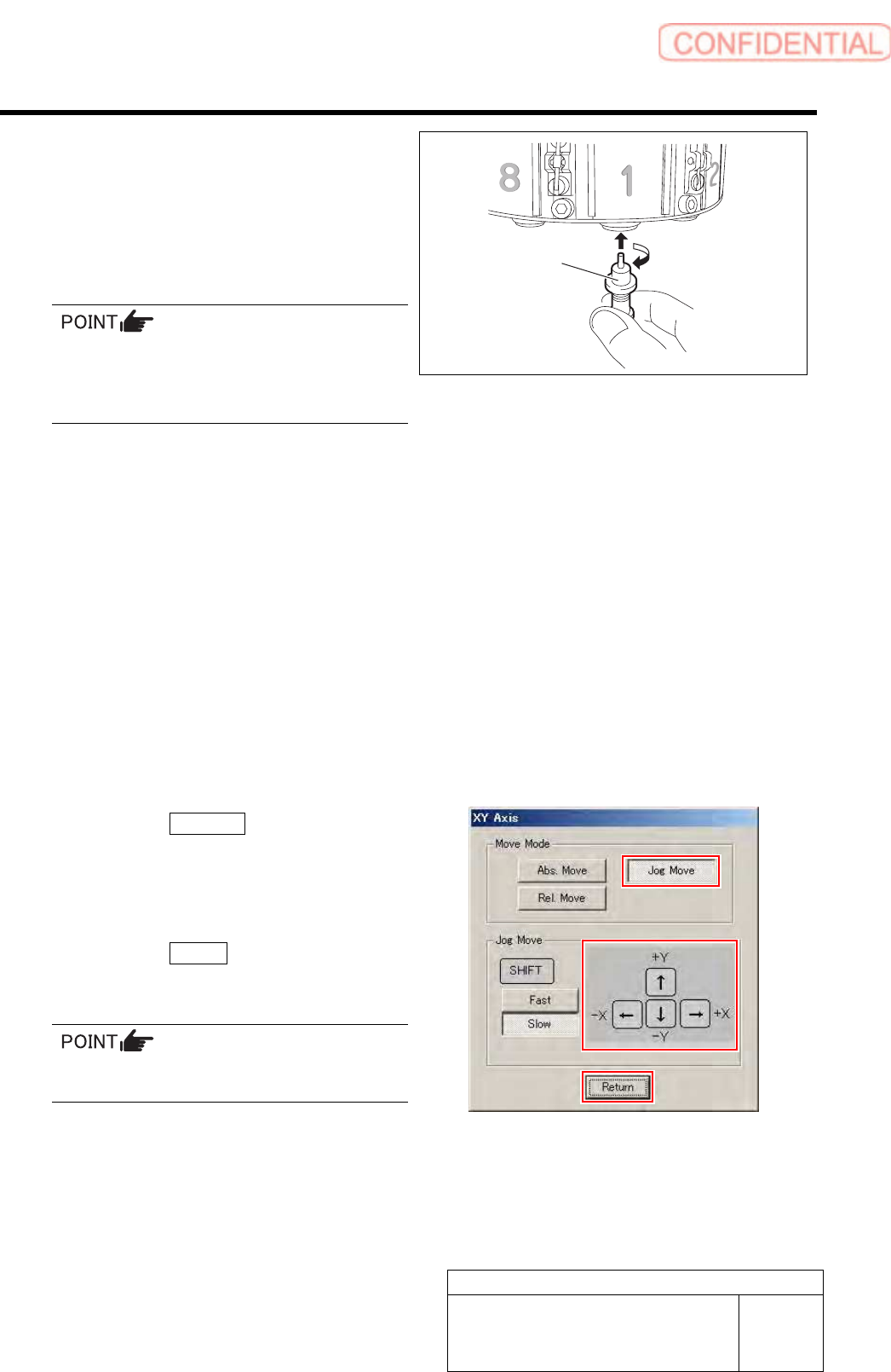
3. Install the length reference nozzle jig
to the turret No.1.
When installing the nozzle, insert it while
slowly turning.
After inserting the nozzle, check that it is not
drawn out by pulling downward.
4. Press the [ORG] button on the
operation panel.
Origin position return is performed and “Move
nozzle tip to fixed camera position” is displayed
on the message screen.
11 Move the length reference nozzle jig
installed on the turret No.1 onto the fixed
camera jig base.
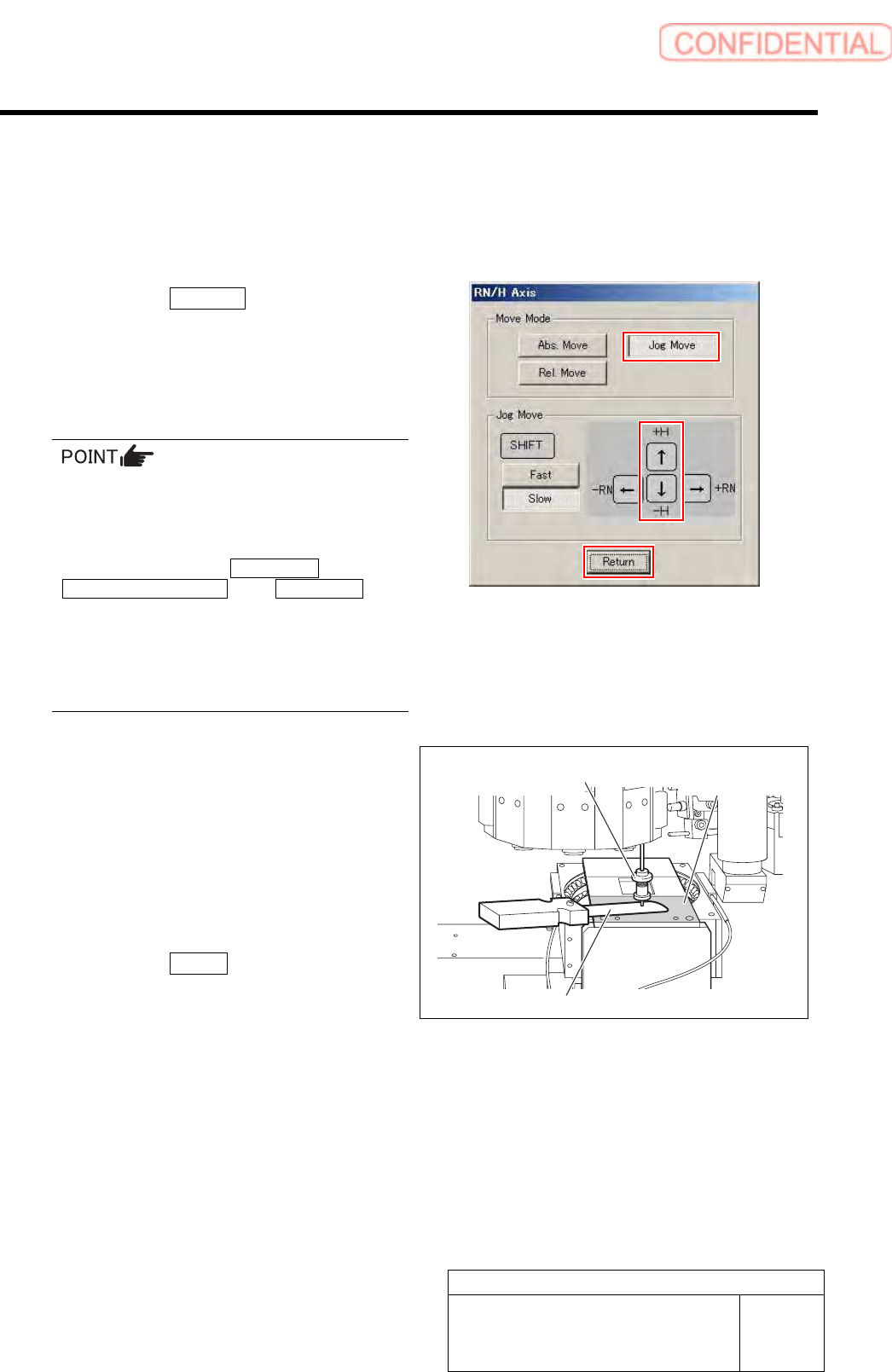
1. Press the [START] button on the
operation panel.
XY Axis screen is displayed.
2. Click the Jog Move button.
3. Press the cursor keys to jog move the
length reference nozzle jig onto the
fixed camera jig base (high level
difference face).
4. Click the Return button.
“Move nozzle tip to recognition height” is
displayed on the message screen.
If the Shift key on the keyboard is pressed,
Fast/Slow for Jog Move can be switched.
Length reference
nozzle jig
Calibration
HLGB-10310-01
Fixed Camera Rcg Height Calibration
SHEET
4/5
12 Adjust gap between the fixed camera jig
base and length reference nozzle jig.
1. Press the [START] button on the
operation panel.
RN/H Axis screen is displayed.
2. Click the Jog Move button.
3. Press the downward cursor key to
lower the length reference nozzle jig to
height of 0.03mm above the fixed
camera jig base (high level difference
face).
If any error occurs when lowering the length
reference nozzle jig, change the negative values
of the H axis software limit to remedy as
follows.
Click in an order of the M/C SETUP menu
MOTOR PARAMETER tab Axis param. tab
and change the negative value of H axis
software limit from [-15.0] to [-16.0].
After fixed camera rcg height is completed, be
sure to return the value of software limit to the
original value.
4. Check the gap between the length
reference nozzle jig and fixed camera
jig base (high level difference face)
using thickness gauge of 0.03mm.
5. After adjusting the gap, pull out the
thickness gauge and lower the H axis
by 0.03 mm (three click) by Low speed
Jog Move.
6. Click the Return button.
“Press [START] to display H axis move dialog”
is displayed on the message screen.
13 Press the [START] button on the operation
panel.
The present position of H axis is obtained and returns
to the Fixed Camera Rcg Height screen.
High level
difference face
Length reference
nozzle jig
Thickness gauge
Calibration
HLGB-10310-01
Fixed Camera Rcg Height Calibration
SHEET
5/5
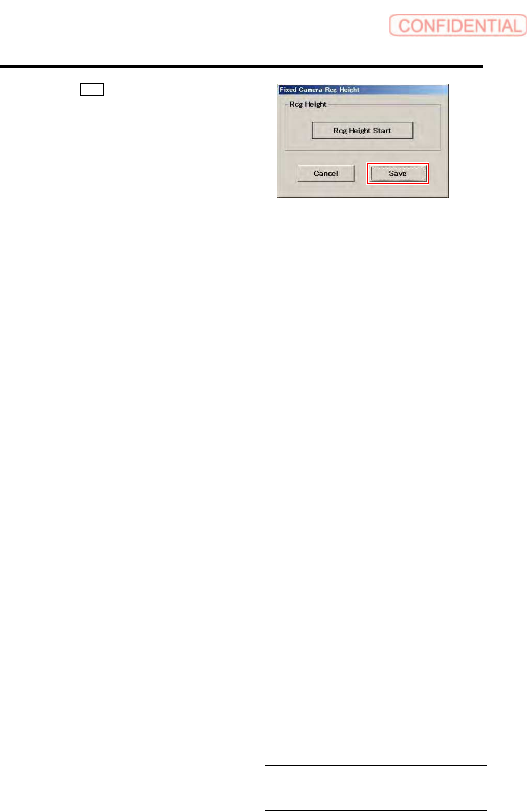
14 Click the Save button.
The fixed camera rcg height is saved and the Fixed
Camera Rcg Height screen closes.
15 Finish fixed camera recognition height search.
1. Close the calibration menu screen to return the unit to the origin.
2. Remove the fixed camera jig base and length reference nozzle jig.
3. Install the cooling fan for fixed camera to the previous position.
4. Install the shooter and the lower cover.