MAN00000772_SI-G200BB_SVCPDFA.pdf - 第116页
Install Tray Unit (Re-setup after tray unit moved) SEET 4/19 WKGB-10105-02 Installing Tray Unit (Re-setup after tray unit moved) [Docking with mounter main body] [Necessary jig and T ools] ・ S p anner(17[mm]) ・ S p anner…
Install Tray Unit (Re-setup after tray unit moved)
SEET
3/19
WKGB-10105-02
Installing Tray Unit
(Re-setup after tray unit moved)
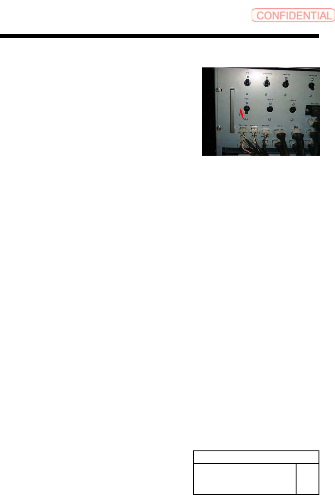
3 Turn ON the TRAY breaker for the rear
power unit.
Install Tray Unit (Re-setup after tray unit moved)
SEET
4/19
WKGB-10105-02
Installing Tray Unit
(Re-setup after tray unit moved)
[Docking with mounter main body]
[Necessary jig and Tools]
・Spanner(17[mm])
・Spanner(24[mm])
・Spanner(30[mm])
・Hex-Wrench(10[mm])
・Scale(300[mm])
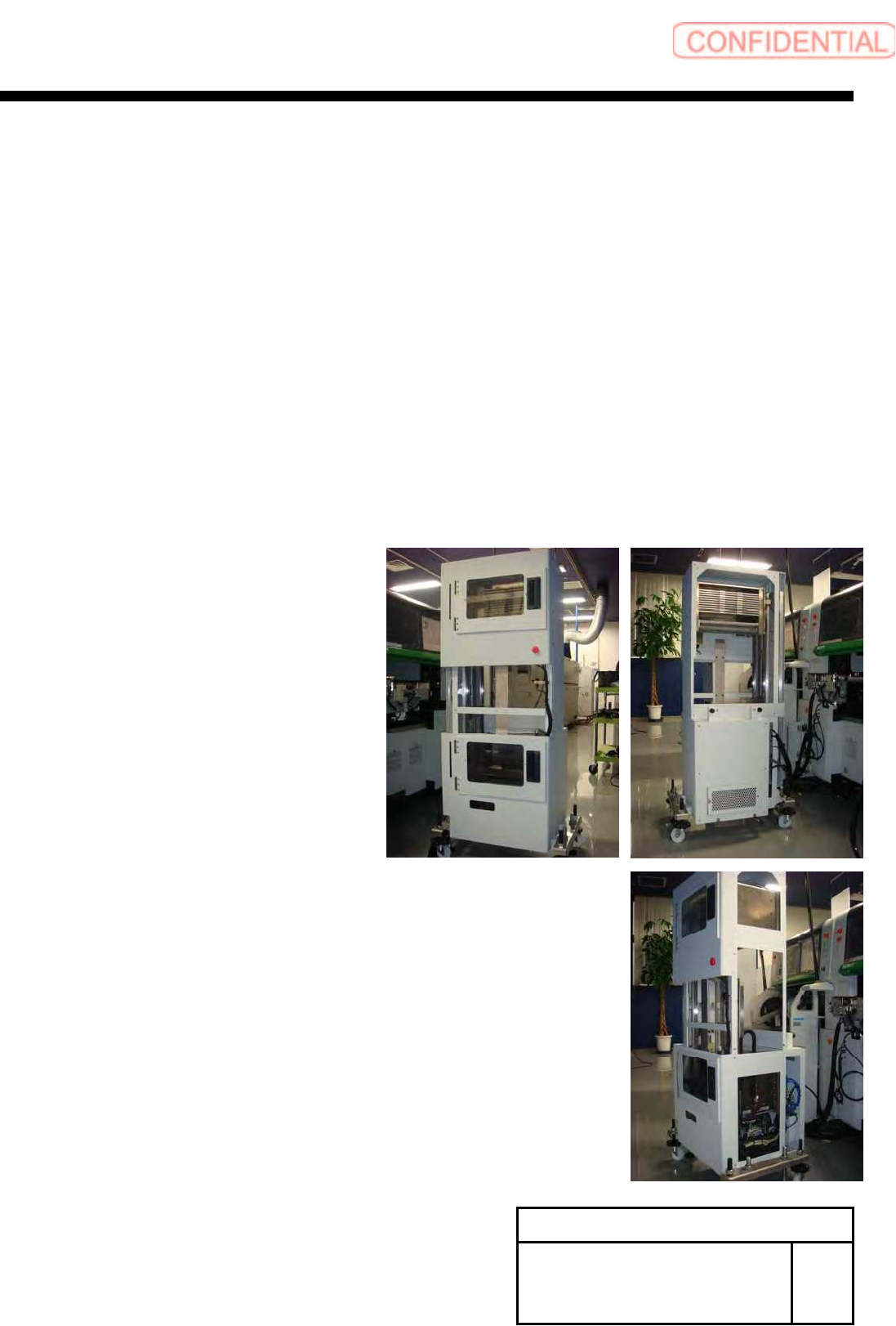
1 Remove front middle cover and rear
upper cover and side upper cover, side
lower cover.
Install Tray Unit (Re-setup after tray unit moved)
SEET
5/19
WKGB-10105-02
Installing Tray Unit
(Re-setup after tray unit moved)
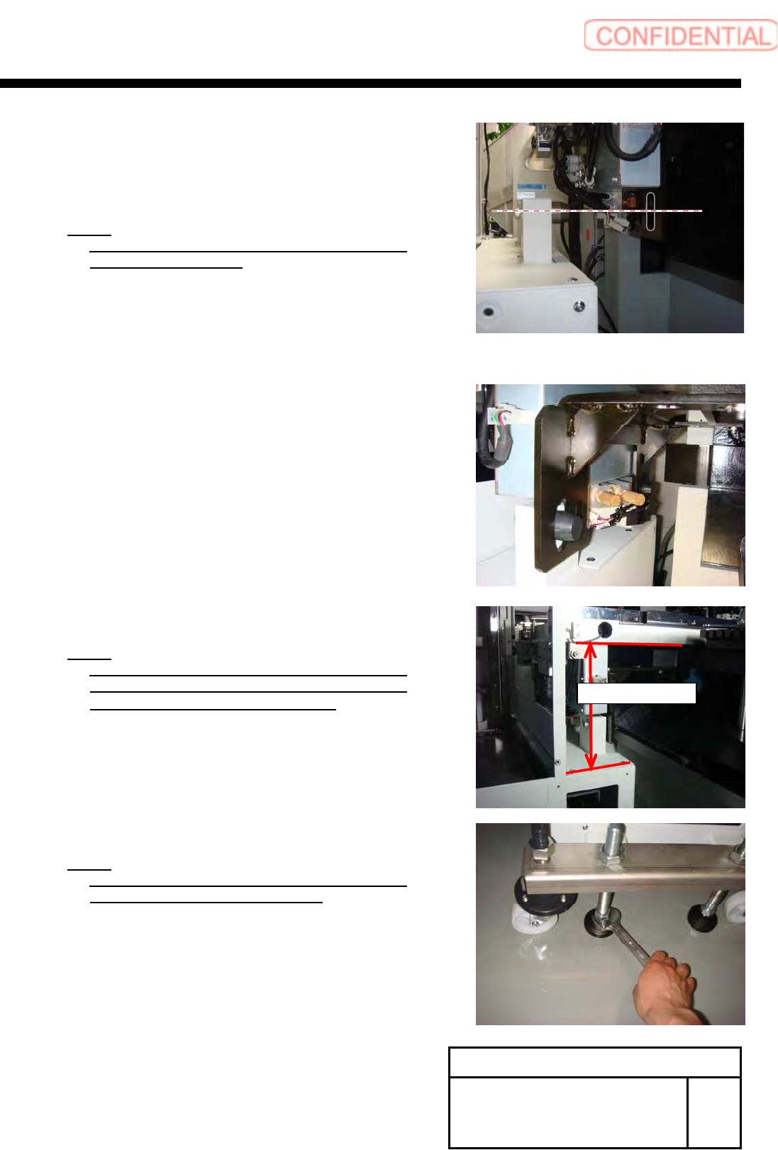
2 Adjust the height of Pin of Tray unit and
long circle hole of mount bracket to
same height.
NOTE:
Adjust four adjuster foot evenly, when change
the height of Tray-unit.
3 Insert the locate pin of tray unit to pin
hole of mount bracket.
4 Adjust height of tray unit.
NOTE:
Adjust height from upper section of the tray
unit electric component cover to bottom of S
axis unit face to 202[mm]~206[mm].
NOTE:
At this time, please confirm the caster of the
tray unit is not touching the floor.
204±2[mm]