MAN00000772_SI-G200BB_SVCPDFA.pdf - 第691页
Ch ange Procedu re fo r Lever A ssembly o f Head Un it 5. Remo v e the pipe f it ting. T hen remove the pickup c heck up/do wn unit. P OI NT Use 7mm wren ch 4 Remov e the 2-C4x 16 and the rail ho lde r. CAUTION Su pport …
Change Procedure for Lever Assembly of Head Unit
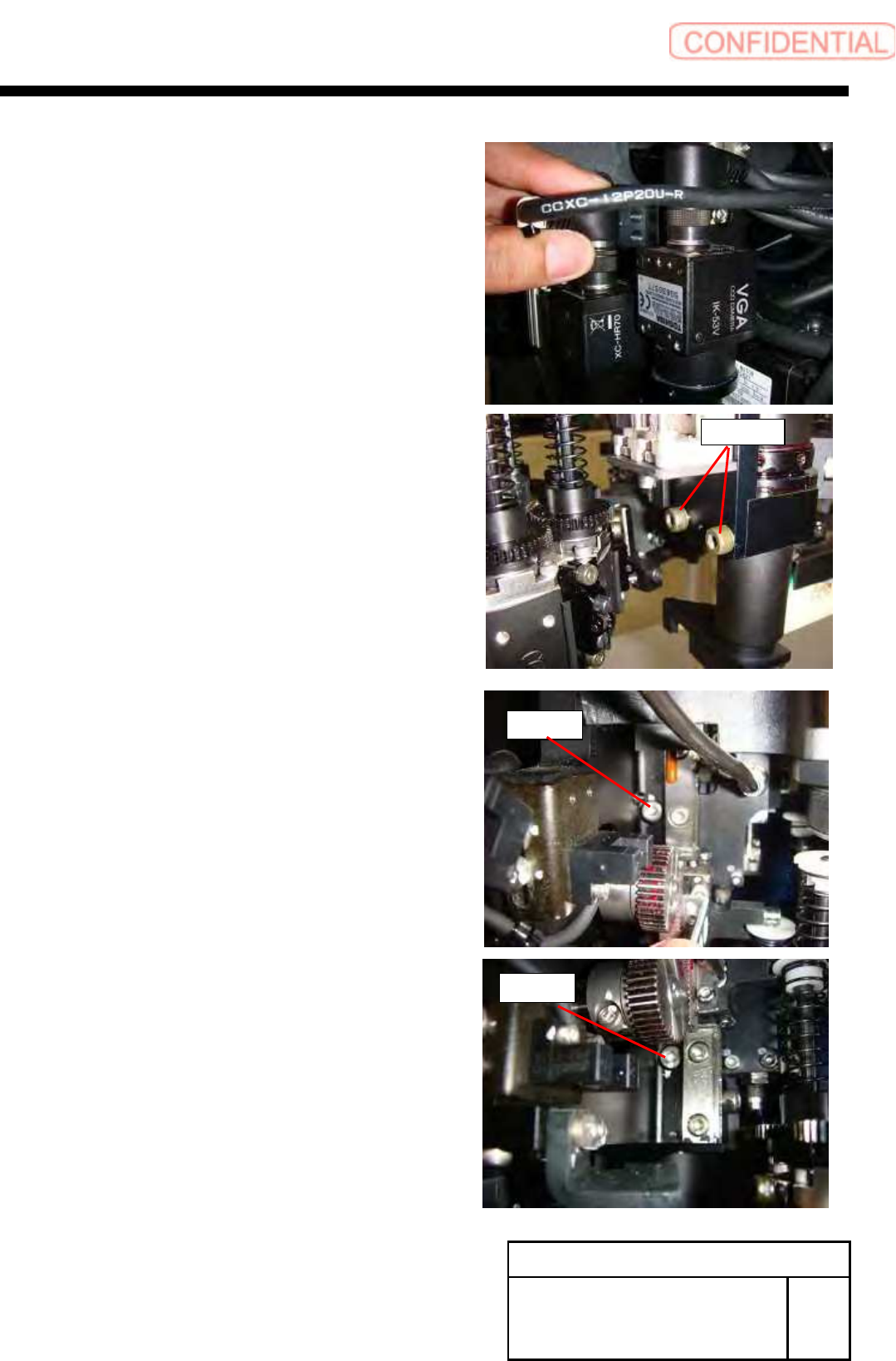
3. Pull out the connector (cam2-U*) of camera cable,
loosen 2-CP4x8, and remove the detection camera.
4. Loosen 2-CP4x6 from the back of the head.
Change Procedure for Head Unit
Lever Assembly
SHEET
2/7
RPGB-11101-1
CP4x8
CP4x6
CP4x6
Change Procedure for Lever Assembly of Head Unit
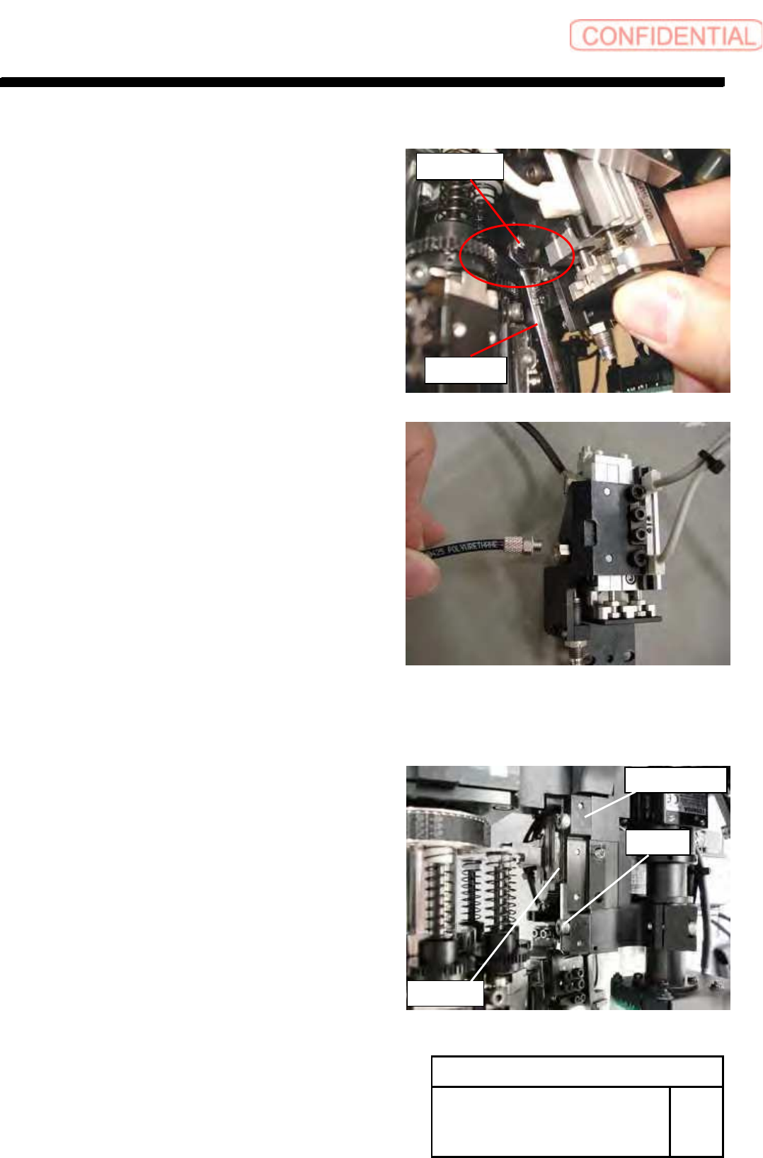
5. Remove the pipe fitting.
Then remove the pickup check up/down unit.
POINT
Use 7mm wrench
4 Remove the 2-C4x16 and the rail holder.
CAUTION
Support the edge of rail when remove the rail holder.
LM guide should not come off for upper side.
After removed it, prevent to come off the tip by cable tie.
Rail Holder
C4x16
LM Guide
Change Procedure for Head Unit
Lever Assembly
SHEET
3/7
RPGB-11101-1
M7 wrench
Pipe Fitting
Change Procedure for Head Unit Lever Assembly
5
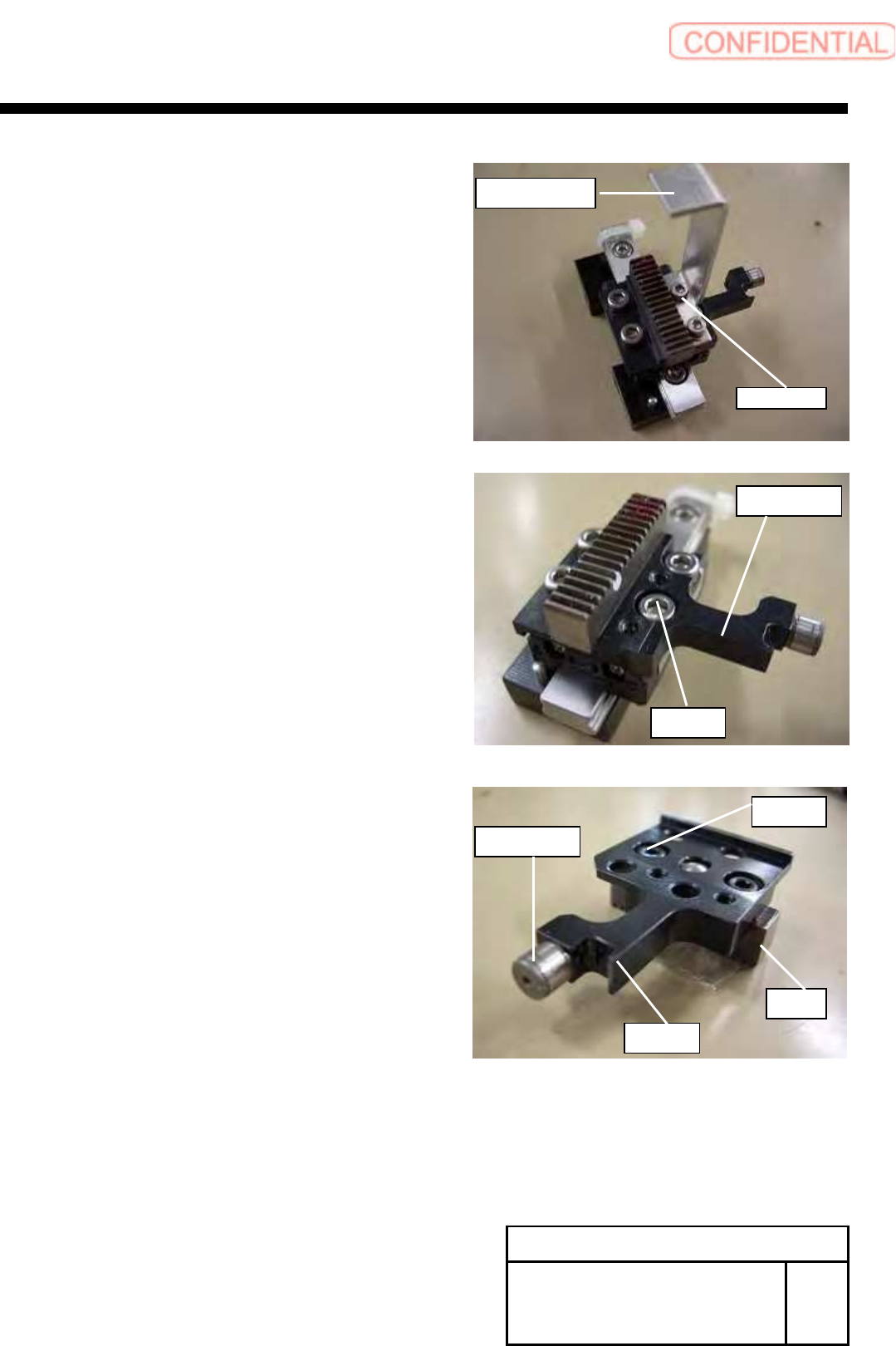
Remove the screws (2-C2.5x5) and H axis sensor dog.
6 Remove the screws (4-C3x4) and Lever assembly.
7 Remove the screws (2-C2.5x4) and rack.
POINT
Replace the cam-follower together when you change lever.
Remove with pliers when you replace only the cam-follower.
Does not come off in wrench because it is glue.
C2.5
x
5
H axis sensor dog
C3x4
Lever ass’y
Change Procedure for Head Unit
Lever Assembly
SHEET
4/7
RPGB-11101-1
C2.5x4
Rack
Lever
Cam-Follower