00193891-0702_AI_LP_Barcode_DE+EN.pdf - 第145页
SIPLACE 2 PCB barcode scanner assembly instructions 10/2009 Edition 2.3 Restrictions 145 2.3.5 SIPLACE HF ser ies / X-series / D3 SIPLACE HF/X series restrictions (1D scanner , beam across direction of travel, 2D scanner…
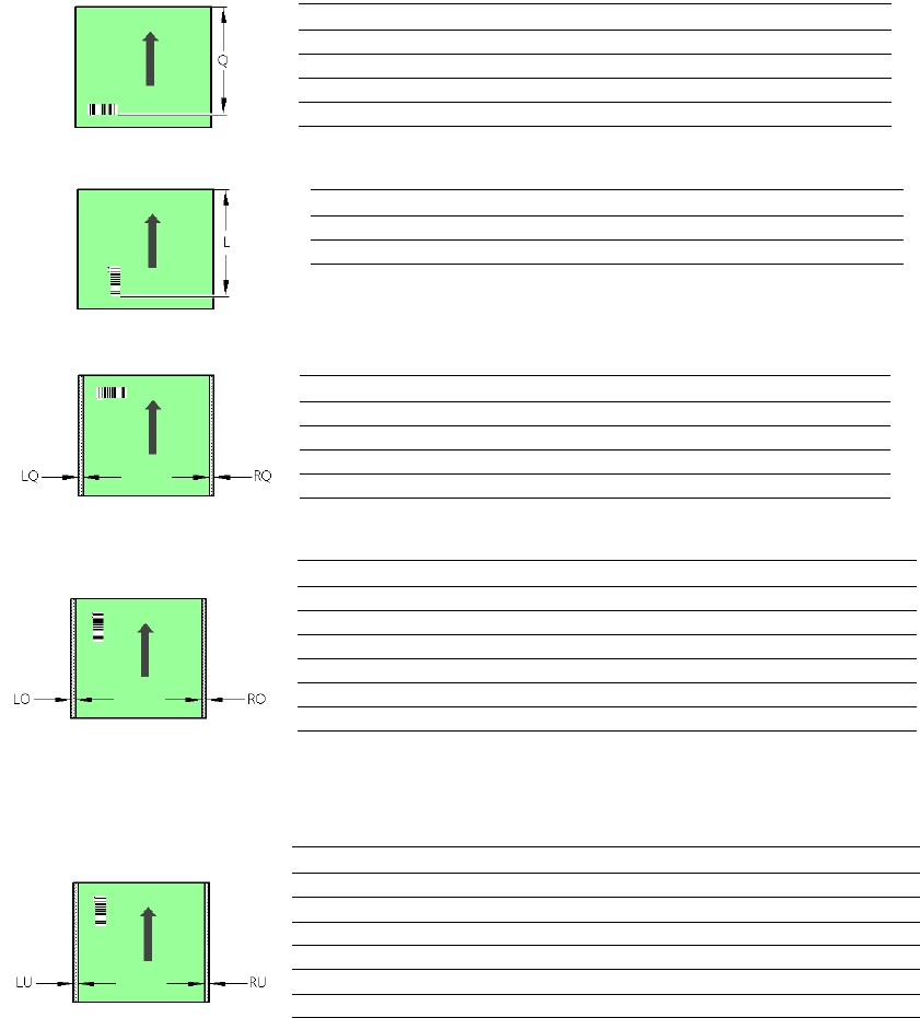
PCB barcode scanner Q [mm]
2D topside 310
1D topside 310
2D underside 310
1D underside 310
PCB barcode scanner L [mm]
1D topside 240 - 310
1D underside 280 - 350
PCB barcode scanner LQ [mm] RQ [mm]
2D topside 3 3
1D topside 3 3
2D underside 5 5
1D underside 5 5
PCB dimensions/conveyor LO [mm] RO [mm]
SC: 460 mm 3 35
SC: 508 mm 3 61
DC1: 216 mm 3 40
DC1: 2x250 mm, SM1: 430 mm 3 66
DC2: 216 mm 3 3
DC2: 2x250 mm, SM2: 430 mm 3 3
1 D PCB barcode scanner topside
PCB dimensions/conveyor LU [mm] RU [mm]
SC: 460 mm 35 5
SC: 508 mm 61 5
DC1: 216 mm 15 5
DC1: 2x250 mm, SM1: 430 mm 15 5
DC2: 216 mm 40 5
DC2: 2x250 mm, SM2: 430 mm 66 5
1D PCB barcode scanner underside
SC Single conveyor
DC1 Dual conveyor, track 1
DC2 Dual conveyor, track 2
SM1 Dual conveyor in Single conveyor mode, track 1
SM2 Dual conveyor in Single conveyor mode, track 2
2 PCB barcode scanner assembly instructions SIPLACE
2.3 Restrictions 10/2009 Edition
144
2
2
2
2
2
2
2
2
2
SIPLACE 2 PCB barcode scanner assembly instructions
10/2009 Edition 2.3 Restrictions
145
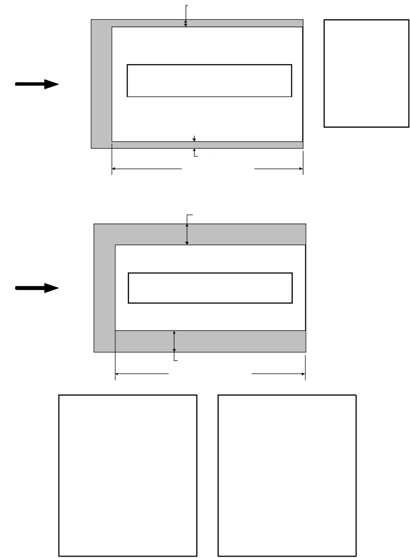
2.3.5 SIPLACE HF series / X-series / D3
SIPLACE HF/X series restrictions (1D scanner,
beam across direction of travel, 2D scanner)
Left
2D topside:
left/right, 3 mm
1D topside:
left/right, 3 mm
2D underside:
left/right, 5 mm
1D underside:
left/right, 5 mm
Right
2D topside, 390 mm
1D topside, 390 mm
2D underside, 430 mm
1D underside, 430 mm
SIPLACE HF/X series
mechanical restrictions
Right
1D topside, 320-350 mm
1D underside, 380-410 mm
1D topside (beam along the
direction of travel:
- Track 1, standard SC, 18":
20 mm right / 3 mm left
- Track 1, optional SC, 20":
44 mm right / 3 mm left
- Track 1, standard DC, 8.5"
24 mm right / 3 mm left
- Track 1, 2x250/1x450 mm DC:
58 mm right / 3 mm left
- Track 2, standard DC, 8.5":
3 mm right / 3 mm left
- Track 2, 2x250/1x450mm" DC:
3 mm right / 3 mm left
1D underside (beam along the
direction of travel:
- Track 1, standard SC, 18":
3 mm right / 20 mm left
- Track 1, optional SC, 20":
3 mm right / 44 mm left
- Track 1, standard DC, 8.5"
3 mm right / 3 mm left
- Track 1, 2x250/1x450 mm DC:
3 mm right / 3 mm left
- Track 2, standard DC, 8.5":
3 mm right / 24 mm left
- Track 2, 2x250/1x450mm" DC:
3 mm right / 58 mm left
Left
2

2 PCB barcode scanner assembly instructions SIPLACE
2.4 Safety instructions 10/2009 Edition
146
2.4 Safety instructions
WARNING
The safety instructions from the Ope
rational safety chapter of the user manual and servicing in-
structions take precedence over th
ese instructions. 2
The SIPLACE placement machines are supplied with mains voltage.
Consequently parts of these systems carry dangerous voltages! This voltage is present at cer-
tain modules inside the machine base, even when the machine is switched off at the main power
switc
h.
Incorrect handling of the placement machine or touching live parts of the machine can result in
death
or severe injury, and considerable damage to equipment.
BEFORE starting any work, shut down the operating system correctly, then switch the machine
OFF at
the main power switch and disconnect from the main power supply. In addition, the com-
pressed air supply must be switched off at the compressed air unit's main valve in the machine
base and v
ented by actuating the needle valve on the compressed air unit.
There is DANGER for heart pacemaker wearers in the vicin
ity of the linear motors, as described
in detail in the "Special safety instructions for working in the vicinity of strong magnetic fields"
section of the user manual and service manual.
Always follow the accident prevention regulations, DIN or other standards and special safety
ru
les applicable in your country.
Pay attention to the information concerning residual voltages in the Operational Safety chapter.
Follow the ESD regulations as described in the operational safety section of the operating
instr
uctions.
During the retrofit, always secure the machine to prevent access by other people and to prevent it
being
switched on again. The procedure is described in the “Locking the machine…” section of
the user manual.
Working with the SITEST program further increases the risk of accident.
The SITEST program must only be used by authorized and trained personnel.
2
2