00193891-0702_AI_LP_Barcode_DE+EN.pdf - 第171页
SIPLACE 2 PCB barcode scanner assembly instructions 10/2009 Edition 2.7 Installing the PCB barcode scanner 171 : Connect the cable Item no.: 03016825-xx for HS-60 / D4 or Item no. 03016827- xx for D1/D2 for the PCB barco…
2 PCB barcode scanner assembly instructions SIPLACE
2.7 Installing the PCB barcode scanner 10/2009 Edition
170
: Fix the cables using cable ties.
2
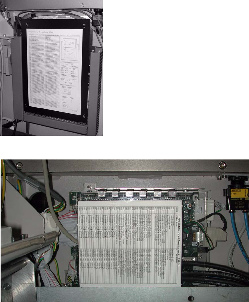
: Open the panel on the left-hand side of the input extension kit.
: Remove the cover from the conveyor control.
2
Fig. 2.7 - 1 HS-60 / D4 conveyor control
2
Fig. 2.7 - 2 D1/D2 conveyor control
SIPLACE 2 PCB barcode scanner assembly instructions
10/2009 Edition 2.7 Installing the PCB barcode scanner
171
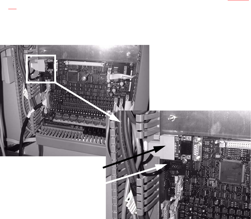
: Connect the cable
Item no.: 03016825-xx for HS-60 / D4 or
Item no. 03016827- xx for D1/D2
for the PCB barcode distributor to the conveyor
control (see also the wiring diagram Section
2.9):
X23
9-pin plug
X24
Power supply (Check the polarization)
Power supply
9-pin plug
2
Fig. 2.7 - 3 HS-60 / D4 conveyor control
Plug
2 PCB barcode scanner assembly instructions SIPLACE
2.7 Installing the PCB barcode scanner 10/2009 Edition
172
2
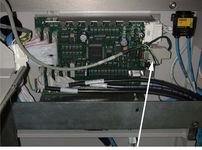
Fig. 2.7 - 4 HS-60 / D4 conveyor control
2
The jumper assignment for the interface (SIPLACE / SMEMA) on the conveyor control must cor-
respond to the current interfaces otherwise the barc
ode data will not be forwarded correctly to the
station software. 2
J1 = SIPLACE/SMEMA upstr
eam station
J2 = SIPLACE/SMEMA downstream station
SIPLACE = setting 1-2; SMEMA setting 2-3. 2