00193891-0702_AI_LP_Barcode_DE+EN.pdf - 第199页
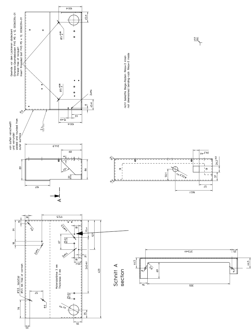
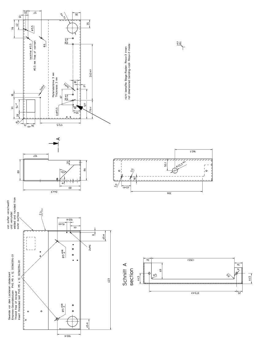
T ap the thread here SIPLACE 2 PCB barcode scanner assembly instructions 10/2009 Edition 2.8 Mechanical drawings 199 2 Fig. 2.8 - 2 Drilling pattern for HS-50 frame, left-hand side ( 00330492-060201)
2 PCB barcode scanner assembly instructions SIPLACE
2.8 Mechanical drawings 10/2009 Edition
198
2.8 Mechanical drawings
Tap the thread
here
2
Fig. 2.8 - 1 Drilling pattern for HS-50 frame, right-hand side (00330491-060201)
Tap the thread
here
SIPLACE 2 PCB barcode scanner assembly instructions
10/2009 Edition 2.8 Mechanical drawings
199
2
Fig. 2.8 - 2 Drilling pattern for HS-50 frame, left-hand side (00330492-060201)
2 PCB barcode scanner assembly instructions SIPLACE
2.9 Electrical drawings 10/2009 Edition
200
2.9 Electrical drawings
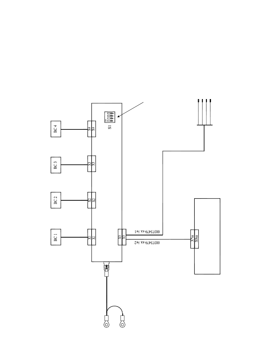
Distributor f. PCB barcode scanner 00372356-xx
Barcode scanner
top
Conveyor track 1
Barcode scanner
bottom
Conveyor track 1
Barcode scanner
top
Conveyor track 2
Barcode scanner
bottom
TConveyor track 2
If no barcode scanner is connected to X1 ... X4,
Use caps to cover slots that are not used.
PCB barcode, conveyor track 1
Machine controller
PCB barcode, conveyor track 2
Wiring for S/F PCB barcode scanner
GN
BN
WH
YE
X212/4
X2kc:7
X212/3
X2kc:4
Connecting the terminal panel (left-hand side)
+24V
IO terminal A2 (Start signal, track 1)
GND
IO terminal A2 (Start signal, track 2)
03022166-xx
Extension kit
Replace grounding cable 00310192-xx by 03022166-xx.
Frame
Distributor grounding terminal
make sure to set the associated switch contact 1 ... 4 at S1 to ON.
2
Fig. 2.9 - 1 Wiring for PCB barcode scanner S/F (03016203-010301)