00193891-0702_AI_LP_Barcode_DE+EN.pdf - 第266页
2 PCB barcode scanner assembly instructions SIPLACE 2.12 Tips & tricks for the barcode scanner 10/2009 Edition 266 2.12.9 Import ant setup set tings for the ICR850 2 2 It is possible that the lens speed used for the …
SIPLACE 2 PCB barcode scanner assembly instructions
10/2009 Edition 2.12 Tips & tricks for the barcode scanner
265
2.12.8 Changes in the CLV wizard
The graphical representation for setting the scanners and the focus height have changed in ver-
sion 4.2 of the CLV Setup software. 2
2
For a detailed description, see:
00193891-xx Retrofit instructions for PCB barcode, se
ction 1.11.6.5 Working with the CLV wiz-
ard 2
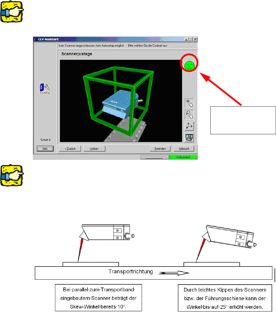
The illustration shows
the display if the scan-
ner is set correctly.
2
2
If problems occur when scanning data matrix code, even though the scanner is set correctly, then
the scanner should be set up with a skew angle of up to 25°. 2
This is particularly recommended
with low-contrast codes (e.g. CO2 or Nd-YAG lasered). 2
In this case, the focus height can
not be determined using the CLV wizard, however, and must be
set manually using the gauge supplied. 2
2
2 PCB barcode scanner assembly instructions SIPLACE
2.12 Tips & tricks for the barcode scanner 10/2009 Edition
266
2.12.9 Important setup settings for the ICR850
2
2
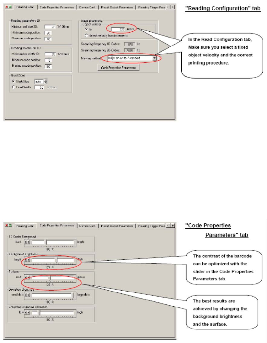
It is possible that the lens speed used for the first station on a line cannot be the same as for the
other stations. This is because the conveyor belt upstream of the first station often travels faster
or slower than the SIPLACE conveyor and, at the time of scanning, still determines the speed of
the PCB. The SIPLACE conveyor runs at around 300-350 mm/s. The selected marking method
determines the contrast of the barcode and thus whether decoding will be successful. Many prob-
lems occur, for example, only when an attempt is made to scan a CO2-lasered code with a default
sett
ing. 2
2
2
SIPLACE 2 PCB barcode scanner assembly instructions
10/2009 Edition 2.12 Tips & tricks for the barcode scanner
267
2
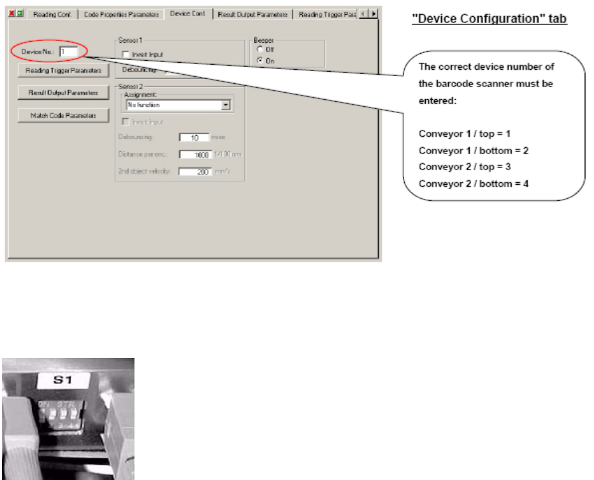
It is also important that the scanner hardware is connected at the correct slot of the HUB and that
the DIP switches are set correctly. 2
Scanners connected to the barcode distributor must be set to
"OFF" at the DIP switch, scanners not connected to the bar-
code distributor must be set to "ON".
2
2
2
2
2
2
2