00193891-0702_AI_LP_Barcode_DE+EN.pdf - 第198页
2 PCB barcode scanner assembly instructions SIPLACE 2.8 Mechanical drawings 10/2009 Edition 198 2.8 Mechanical drawings T ap the thread here 2 Fig. 2.8 - 1 Drilling pattern for HS-50 frame, right-hand side (00330491-0602…
SIPLACE 2 PCB barcode scanner assembly instructions
10/2009 Edition 2.7 Installing the PCB barcode scanner
197
: Set the distances between the 1D barcode scanner and the PCB so that the barcodes are read
reliably.
This is achieved by moving the cross-rails up or down in the slots.
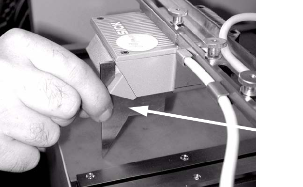
: For the 2D barcode scanner, set to exactly 85 m
m ± 1 mm. Use the setting gauge provided.
The 2D barcode scanner only works in this focus range.
Distance from 2D barcode scan-
ner
to PCB: 85 mm +/- 1 mm.
The SICK software (version >
4.1) can be used to check the set-
ting. 2
Setting gauge
2
2
2
2
2
2
2
2
2
2
2
2
2
2
2 PCB barcode scanner assembly instructions SIPLACE
2.8 Mechanical drawings 10/2009 Edition
198
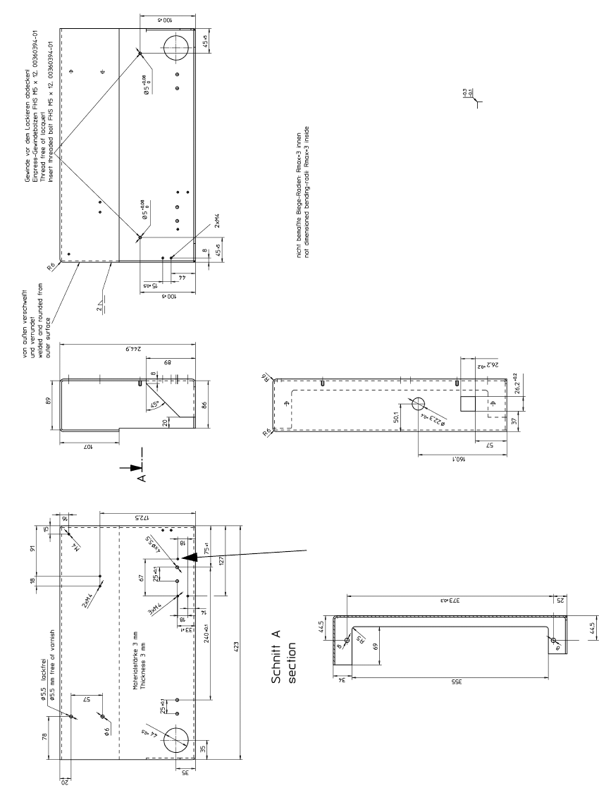
2.8 Mechanical drawings
Tap the thread
here
2
Fig. 2.8 - 1 Drilling pattern for HS-50 frame, right-hand side (00330491-060201)
Tap the thread
here
SIPLACE 2 PCB barcode scanner assembly instructions
10/2009 Edition 2.8 Mechanical drawings
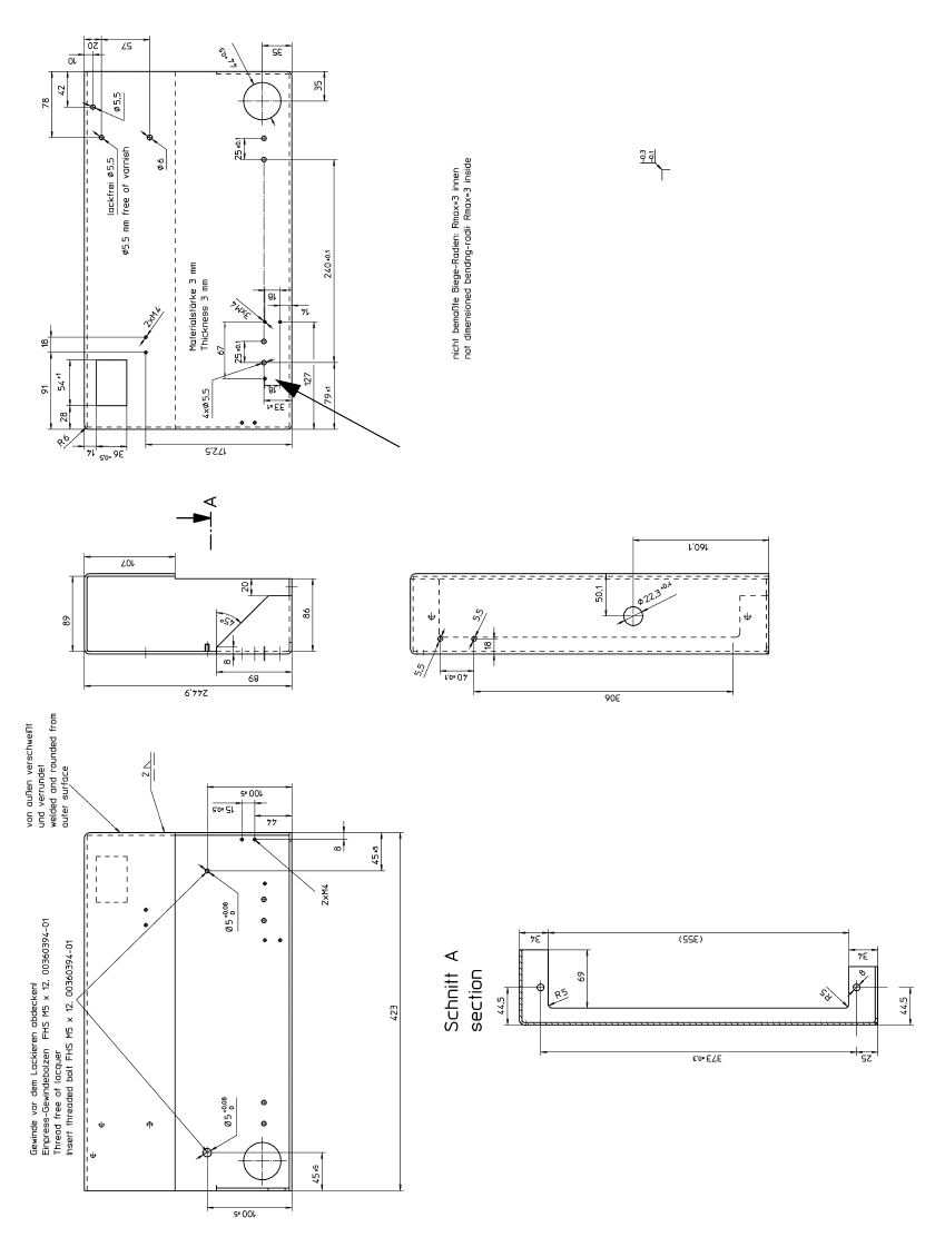
199
2
Fig. 2.8 - 2 Drilling pattern for HS-50 frame, left-hand side (00330492-060201)