00193891-0702_AI_LP_Barcode_DE+EN.pdf - 第240页
2 PCB barcode scanner assembly instructions SIPLACE 2.11 PCB barcode scanner configuration 10/2009 Edition 240 Fig. 2.1 1 - 33 Result window on the right showing the barcode data Fig. 2.1 1 - 34 S tep 6 in the CL V Assis…
SIPLACE 2 PCB barcode scanner assembly instructions
10/2009 Edition 2.11 PCB barcode scanner configuration
239
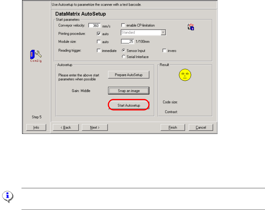
: Click on the "Prepare AutoSetup" button.
The velocity and module size are sent to the barcode scanner.
The "Snap an image" button is now active.
Requirements for snapping the image:
– The machine with the barcode scanner to be configured must be "Waiting for PCB".
– Press the STOP button on the upstream machine.
– Place a PCB with the barcode on the output belt of th
e up
stream machine so that the bar-
code is approximately 1 cm in front of the scanning beam.
: Click on the "Snap an image" button.
: Then press the START button on the upstream machine.
: The "Start Autosetup" butto
n should now be active.
Fig. 2.11 - 32 Step 5 in the CLV Assistant
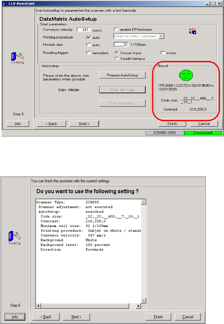
: Click on the "Start Autosetup" button.
If the barcode is read successfully, the data for the con
veyor velocity, module size and optimization
parameters such as contrast, brightness, etc. are determined.
PLEASE NOTE:
These parameters should not be manually changed again.
2 PCB barcode scanner assembly instructions SIPLACE
2.11 PCB barcode scanner configuration 10/2009 Edition
240
Fig. 2.11 - 33 Result window on the right showing the barcode data
Fig. 2.11 - 34 Step 6 in the CLV Assistant
The settings found by the CLV Assistant only apply to this type of barcode.
: Click on "Next". This closes the CLV Assistant.
SIPLACE 2 PCB barcode scanner assembly instructions
10/2009 Edition 2.11 PCB barcode scanner configuration
241
2.11.7.8 Final tasks
: Make all the manual settings as described below.
: The automatically-determined parameters, i.e. co
nveyor velocity and module size and the op-
timization parameters for contrast, brightne
ss, etc. should not be changed again.
: Run a download to the barcode scanner (permanent).
2.11.7.9 Manual setting for the "DEMO" example if you are not using the CLV Assistant
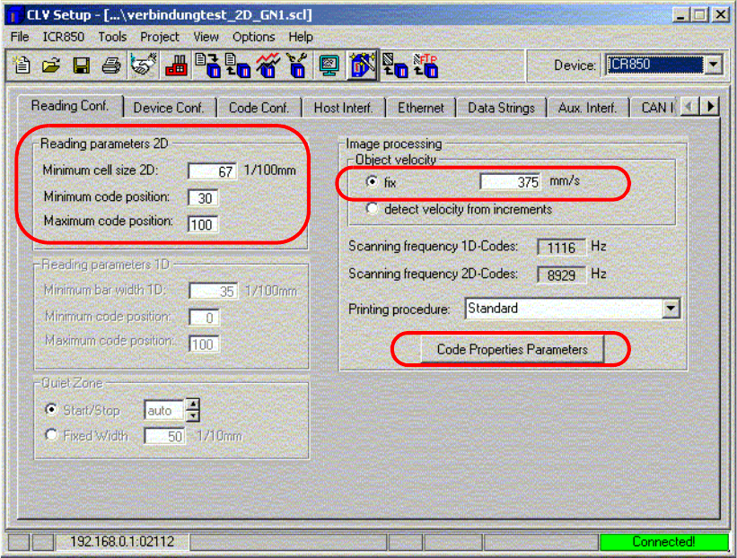
Fig. 2.11 - 35 Reading configuration
: Enter the "Minimum cell size 2D" in 1/100 mm (size of a matrix dot - a tolerance of approx. 30%
is accepted)
e.g. barcode width (12 mm) divided by the number of columns (18)
: Enter the minimum and maximum code position. (Definition
of the size of the scanning win-
dow),
: The object velocity, i.e. the speed with which th
e barcode is scanned, corresponds to the con-
veyor velocity.